Yagi Antenna Element Calculator
Enter your operating frequency and this tool returns the driven element, reflector, and director lengths for a Yagi-Uda beam, using the free-space wavelength lambda = 300 / f in MHz. It also computes element spacing and the total boom length so you can build a full directional antenna from a single frequency in metric or imperial units.
🎯Real Band Presets
📡Antenna Inputs
Center frequency of your band, in the unit selected next.
GHz values are converted to MHz internally.
Parasitic elements in front of the driven element.
Controls how every length is displayed.
Fraction of lambda for the fed element, typically 0.46 to 0.48.
Reflector is about 5 percent longer than driven.
First director length as a fraction of lambda.
Gap between successive elements as a fraction of lambda.
🔢Design Snapshot
📋Element Length Reference by Band
| Band / Use | Frequency | Driven 0.47λ | Reflector 0.495λ | Director 0.44λ |
|---|---|---|---|---|
| 10 m amateur | 28 MHz | 5.04 m | 5.30 m | 4.71 m |
| 6 m amateur | 50 MHz | 2.82 m | 2.97 m | 2.64 m |
| FM broadcast | 100 MHz | 1.41 m | 1.49 m | 1.32 m |
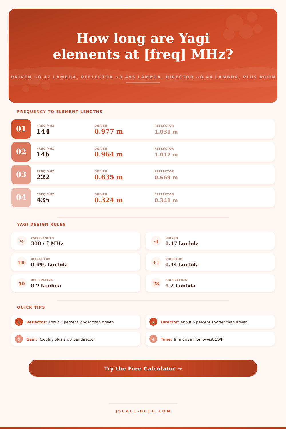
| 2 m amateur | 144 MHz | 0.979 m | 1.031 m | 0.917 m |
| 1.25 m amateur | 222 MHz | 0.635 m | 0.669 m | 0.595 m |
| 70 cm amateur | 435 MHz | 0.324 m | 0.341 m | 0.303 m |
| ISM band | 915 MHz | 0.154 m | 0.162 m | 0.144 m |
| ADS-B receive | 1090 MHz | 0.129 m | 0.136 m | 0.121 m |
📏Spacing Guidelines (fraction of lambda)
| Gap | Low End | Typical | High End | Effect |
|---|---|---|---|---|
| Reflector to driven | 0.15 λ | 0.20 λ | 0.25 λ | Front-to-back ratio |
| Driven to director 1 | 0.07 λ | 0.10 λ | 0.15 λ | Feed impedance |
| Director to director | 0.15 λ | 0.20 λ | 0.30 λ | Forward gain |
| Wide-spaced boom | 0.20 λ | 0.25 λ | 0.35 λ | Higher gain per element |
| Compact boom | 0.10 λ | 0.15 λ | 0.20 λ | Shorter physical boom |
| Full-wave stack step | 0.50 λ | 0.62 λ | 0.75 λ | Stacking two Yagis |
📡Director Taper Schedule
| Element | Factor x lambda | At 144 MHz | At 435 MHz | Role |
|---|---|---|---|---|
| Reflector | 0.495 | 1.031 m | 0.341 m | Reflects rearward |
| Driven | 0.470 | 0.979 m | 0.324 m | Fed by coax |
| Director 1 | 0.440 | 0.917 m | 0.303 m | Focuses forward |
| Director 2 | 0.435 | 0.906 m | 0.300 m | Adds gain |
| Director 3 | 0.430 | 0.896 m | 0.297 m | Adds gain |
| Director 4 | 0.428 | 0.892 m | 0.295 m | Narrows beam |
| Director 5+ | 0.425 | 0.885 m | 0.293 m | Diminishing gain |
🗃Full Yagi Build Comparison Grid
| Frequency | Wavelength | Driven | Reflector | Director | Directors | Boom Length |
|---|---|---|---|---|---|---|
| 28 MHz | 10.71 m | 5.04 m | 5.30 m | 4.71 m | 2 | 6.43 m |
| 50 MHz | 6.00 m | 2.82 m | 2.97 m | 2.64 m | 3 | 4.20 m |
| 100 MHz | 3.00 m | 1.41 m | 1.49 m | 1.32 m | 3 | 2.10 m |
| 144 MHz | 2.083 m | 0.979 m | 1.031 m | 0.917 m | 4 | 1.771 m |
| 222 MHz | 1.351 m | 0.635 m | 0.669 m | 0.595 m | 5 | 1.351 m |
| 435 MHz | 0.690 m | 0.324 m | 0.341 m | 0.303 m | 6 | 0.759 m |
| 915 MHz | 0.328 m | 0.154 m | 0.162 m | 0.144 m | 8 | 0.459 m |
| 1090 MHz | 0.275 m | 0.129 m | 0.136 m | 0.121 m | 8 | 0.385 m |
| 2400 MHz | 0.125 m | 58.8 mm | 61.9 mm | 55.0 mm | 10 | 0.213 m |
⚙Formula Breakdown
💡Build and Tuning Tips
You can spot the traditional-looking pointed-beam antenna, or Yagi-Uda antenna, on radio amateur towers and rooftops around town. It has parasitic rods added in a straight line from the dipole (usually called the fed element) to increase gain. These is the reflector(s) directly behind the fed element, and one or more directors ahead of it. Getting all these elements cut correctly to the proper length with respect to the wavelength is essential to the entire design, which is precisely what this Yagi antenna element calculator does. Simply feed it a frequency and it will spit out driven element, reflector, first director and total boom length in a single pass.
The thing with antennas is they’re all scaled to the wavelength of whatever signal they carry. That’s just lambda = 300 divided by frequency in megahertz (simple), right? (That’s because light travels roughly 300 million meters/second and we round that off to an easy number.) So that means your 144 MHz antenna have a wavelength of 2.083 meters out in free space, but shrinks down to around 0.69 meters at 435 MHz. Since a Yagi is a collection of tuned rods, each one is described as some fraction of that wavelength value. The rods are therefore meter-long on a two-meter beam and only a couple of cm long on a 2.4 GHz beam.
How to Calculate Yagi Antenna Sizes
There are three kinds of elements on a Yagi that are purposely made to be different lengths. Only one is directly connected to your feed line, and it is called the driven element. This is about 0.47 times lambda long. Due to the other parasitic elements around it, this shifts resonance just enough to make it a hair short of half a wave.
Next up is the reflector which is positioned behind the driven element. It is the longest rod, being roughly five percent longer than the driven element at about 0.495 times lambda. It pushes energy forward by re-radiating slightly out of phase.
Then there are directors which is positioned in front and are the shortest rods. These are about five percent shorter than the driven element, or about 0.44 times lambda. They pull beam forward into a tight lobe.
Spacing determines how everything fits and works together. It also determines what length boom will be needed to support elements. Length tunes each one separately. A typical beginning configuration places the reflector between 0.15 to 0.25 wavelengths behind the driven element. The first director is positioned roughly 0.1 wavelengths ahead, with successive ones being 0.15 to 0.2 wavelengths past the previous one. The combined length of all those spaces is total boom length. This calculator computes that for you. Simply specify the number of directors and a fraction-of-wavelength value for their spacing. It will then tell you the total boom length from reflector to the last director so you can order appropriate tubing.
There are other ways that affect gain; for example, the length of elements, which is limited by frequency; or the number of directors, the single largest way to change gain on a Yagi. For instance, a three-element Yagi (one director, one driven element and one reflector) already has significant forward gain compared too a plain dipole. As a rough rule of thumb each additional director add about one decibel of forward gain. Of course, as the antenna gets longer and its boom stretches out, the returns diminish. At 435 MHz, you get something like well beyond 12 dBi from a long ten-element beam, but every subsequent director contributes much less than the early ones. So this tool would of guessed the overall element count and tries to give you an approximation of gain, to let you balance gain against physical size.
The directors aren’t all the same length either. Following directors gradually decrease their length somewhat while the first one is longest (about 0.44 lambda). By the fifth or sixth director they will have tapered down to around 0.43 lambda. The gradual shortening of the directors smoothes out the pattern and also widens the usable bandwidth. A sample taper schedule is shown in the reference tables here. This shows how an actual multi-element beam steps down in length from front to back. You can still use just one director length across the board as a quick first cut, which still makes for a working antenna, but then you refine it later.
This calculator lets you enter frequency in gigahertz (or megahertz if you want) and it outputs all dimensions in imperial (or metric). For example, if you’re building a microwave project, such as a 2.4 GHz WiFi beam, switch to gigahertz, and it’ll convert to megahertz on the inside to use lambda = 300 divided by frequency but still give you everything out in metric or imperial. If you’d rather have everything in imperial, select that option and it will convert meters into feet/inches, which can be useful if you use a tape measure for marking tubing stock. Short elements display automatically in inches or millimeters. This means you don’t have to remember fractions of a meter, so a 58 millimeter director won’t get lost in a half-meter fraction.
This is not the final cut list, but it is a good starting place for the number this tool generates. It’s basic math and all assumes free space with no thickness of elements. Of course real elements are not infinitely thin and as you run some sort of metal boom around them, it alters their tuning characteristics and typically makes them behave like they are longer. The work-around for that is just to make the elements a couple percentage points longer. Then trim and then watch an SWR meter as you trim in small increments until you find the lowest one right on top of where you want it. Anything that goes through a metal boom couples to it and needs to be set up on insulators or made ever so slightly longer.
The numbers aren’t so scary. The return is real directional gain you can actualy detect on-the-air. Working up a Yagi is a satisfying exercise. Select your frequency. Set your preset to match your band. Pull out the four card results for boom, director, reflector and the driven element. Change the number of directors to trade off size and gain. Refer to the spacing charts, then move to the work bench with a cut length that’s close-enough to be tuned-up in minutes. You can build a wide range of sizes from a target frequency, whether it’s a large six meter array or a small 70 centimeter beam.