Half Wave Dipole Length Calculator
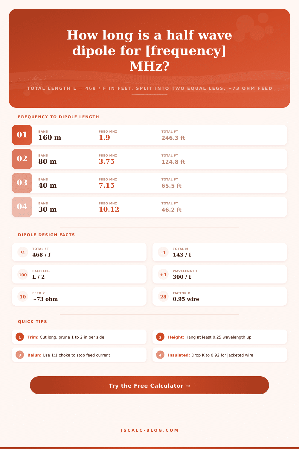
Size a half wave dipole antenna from its resonant frequency. This tool computes the total wire length with the classic L = 468 / f formula in feet, splits it into two equal legs from the feedpoint, reports the full free-space wavelength, and lets you tune the velocity factor K for bare, insulated, or thick conductors, with the nominal 73 ohm feed impedance for reference.
🎯Ham Band and Wire Presets
📡Dipole Design Inputs
The design frequency where the dipole is a half wavelength.
GHz values are converted to MHz internally.
End-effect shortening built into the length constant.
0.95 to 0.96 for thin wire, lower for thick or insulated.
Controls the main length card headline unit.
In meters. Affects feed impedance estimate, not length.
Rounding applied to every result card.
🔢Formula Snapshot
📋Amateur Band Dipole Lengths
| Band | Center Freq | Total Length (468/f) | Each Leg |
|---|---|---|---|
| 160 m | 1.900 MHz | 246.3 ft (75.1 m) | 123.2 ft (37.5 m) |
| 80 m | 3.750 MHz | 124.8 ft (38.0 m) | 62.4 ft (19.0 m) |
| 40 m | 7.150 MHz | 65.5 ft (20.0 m) | 32.7 ft (10.0 m) |
| 30 m | 10.125 MHz | 46.2 ft (14.1 m) | 23.1 ft (7.0 m) |
| 20 m | 14.175 MHz | 33.0 ft (10.1 m) | 16.5 ft (5.0 m) |
| 17 m | 18.118 MHz | 25.8 ft (7.9 m) | 12.9 ft (3.9 m) |
| 15 m | 21.225 MHz | 22.0 ft (6.7 m) | 11.0 ft (3.4 m) |
| 10 m | 28.400 MHz | 16.5 ft (5.0 m) | 8.2 ft (2.5 m) |
📏Velocity Factor K by Conductor
| Conductor Type | Typical K | Length Constant (ft) | Notes |
|---|---|---|---|
| Thin bare wire (VHF) | 0.96 | 472 | Least end effect |
| Bare copper HF wire | 0.95 | 468 | Classic default |
| PVC insulated wire | 0.92 | 453 | Jacket lowers speed |
| Thick aluminum tubing | 0.90 | 443 | High diameter to length |
| Fat elements / cage | 0.88 | 434 | Very low ratio |
| Ideal free-space half wave | 1.00 | 492 | No end effect |
📡Feed Impedance vs Height Over Ground
| Height (wavelengths) | Approx Feed Z | SWR on 50 ohm | Pattern Note |
|---|---|---|---|
| Free space | 73 ohm | 1.46 : 1 | Ideal doughnut |
| 0.125 lambda | ~40 ohm | 1.25 : 1 | High-angle NVIS |
| 0.25 lambda | ~55 ohm | 1.10 : 1 | Cloud warmer |
| 0.375 lambda | ~65 ohm | 1.30 : 1 | Balanced lobes |
| 0.5 lambda | ~70 ohm | 1.40 : 1 | Lower takeoff |
| 1.0 lambda | ~73 ohm | 1.46 : 1 | Multiple lobes |
🗃Frequency to Length Comparison Grid
| Freq MHz | Wavelength (m) | Total (m) | Total (ft) | Each Leg (ft) | Total (in) |
|---|---|---|---|---|---|
| 1.9 | 157.9 | 75.26 | 246.3 | 123.2 | 2956 |
| 3.75 | 80.0 | 38.13 | 124.8 | 62.4 | 1498 |
| 7.15 | 41.96 | 20.00 | 65.5 | 32.7 | 786 |
| 10.125 | 29.63 | 14.12 | 46.2 | 23.1 | 555 |
| 14.175 | 21.16 | 10.09 | 33.0 | 16.5 | 396 |
| 21.225 | 14.13 | 6.74 | 22.0 | 11.0 | 265 |
| 28.4 | 10.56 | 5.04 | 16.5 | 8.2 | 198 |
| 52.0 | 5.77 | 2.75 | 9.0 | 4.5 | 108 |
| 146.0 | 2.05 | 0.98 | 3.2 | 1.6 | 38.5 |
| 446.0 | 0.67 | 0.32 | 1.05 | 0.52 | 12.6 |
⚙Formula Breakdown
💡Build and Tuning Tips
In radio work, reference antenna is the half wave dipole. It consists of one straight conductor cut to half a wavelength, with the feed point in the center split evenly into two legs of equal length. This is where most gain figures gets quoted. This is almost every starting point when building a wire antenna.
And the calculator on this page convert those bits of physics into three number that you’ll have at the bench. First, determine total length of wire to cut. Second, find the length of each leg from the feedpoint. Third, find the full free-space wavelength for context. Then you can tunes the velocity factor to match actual wire in your hands.
How to Build a Half Wave Dipole Antenna
For best efficiency, an antenna has to be the right physical length to be the same electrical length as the radio frequency it is intended to capture. A half wavelength conductor will have a standing wave across it with voltage maxes on each end and a current max in the center. It couples energy into free space predictably and efficienty. The point of maximum current mean the dipole is fed in the center. The feedpoint is located where the impedance is lowest and most easly matched. For a resonant half wave far off the ground it hangs around 73 ohms.
You may have seen: total length in feet = 468 ÷ frequency in megahertz. That’s the most quoted formula in antenna building. If you use 492 ÷ frequency, that’s a pure half wavelength in free space. But real wire isn’t in free space. There is charge that piles up at the open ends of the wire, which causes wave to slow down slightly. This results in the antenna behaving like it’s a few percent longer then what it really is. So to remain resonant, you have to make it shorter. The constant 468 already bakes in a shortening factor of about 0.95. The metric version of rule is 143 ÷ frequency for meters.
The dipole is fed in the middle so each leg is half of overall length. So for a 20 meter dipole on 14.175 MHz that turns out to be around 33 feet total. That means each leg will end up around 16.5 feet long. Why does this matter? Because when you go to build it, you’ll have two equal pieces of wire, attach one end to an insulator in the center then run the other ends to support. The symmetric legs maintains a symmetric radiation pattern. They also keep the feed point impedance where you’d expect it.
Measure twice. Crimp once. Thin bare wire is assumption behind the 468 constant. Not all antennas are like that. A wire with insulation slows the wave, lowering its effective velocity factor. PVC jacketed wire behaves more like a factor of 0.92. You should of shorten it even further. Low length to diameter ratios pulls the factor down for thick aluminum tubing. They pull the factor down toward 0.90. Using custom sizes lets you set your own value. You get that flexibility, bridging the gap between textbook theory and local hardware stores.
The tool shows the factor right out front. You can load a sensible default by picking a conductor type on the menu. In addition to cut length, the calculator shows the full free-space wavelength. That’s good for a reality check. How much real estate does this thing take up in wavelengths? And, how high should I hang it?
A resonant half wave dipole in free space has an impedance of around 73 ohms pure resistance. In the real world, antennas hangs above ground, which acts like a reflector and alters the feedpoint impedance. At less than a quarter wavelength off the ground, the impedance lower. This also helps improve the match to a typical 50 ohm feedline in most installations. That’s where you start. It isn’t where you finish.
Surroundings will change your resonance slightly as well as the wire you use to make it. Cut each leg about 2% too long. Rig up your antenna at normal operating height. Next take off an inch or so of each end while watching the analyzer. The higher the resonant frequency, more you take off. It’s pretty linear. Making small symmetrical cuts lets you tune fine. With this approach you quickly find yourself exactly at the starting point.
And yet there’s still one last step: Tuning it in flight.