Quarter Wave Antenna Calculator
Design a quarter-wave vertical monopole or ground-plane antenna. Enter the operating frequency and velocity factor, and get the driven element length in millimetres, centimetres, feet and inches, along with the recommended radial length and the full free-space wavelength for your band.
📡Popular Band Presets
🔧Antenna Design Inputs
Center frequency of your band or channel.
GHz is handy for WiFi and microwave links.
Presets the end-effect factor for common builds.
Fraction of the ideal quarter wave, 0.95 typical.
Four or more is common for a 50 ohm match.
Radials cut about 5 percent longer than the vertical.
Sets which unit the first result card leads with.
Controls rounding on the result cards.
🔢Formula Snapshot
📡Frequency to Quarter-Wave Length
| Band / Service | Frequency | Element (m) | Element (ft-in) |
|---|---|---|---|
| CB channel 20 | 27.185 MHz | 2.62 m | 8 ft 7 in |
| 10m amateur | 28.4 MHz | 2.51 m | 8 ft 3 in |
| 6m amateur | 50.15 MHz | 1.42 m | 4 ft 8 in |
| Airband VHF | 127 MHz | 0.561 m | 1 ft 10 in |
| 2m amateur | 146 MHz | 0.488 m | 1 ft 7 in |
| Marine VHF ch16 | 156.8 MHz | 0.454 m | 1 ft 6 in |
| 70cm amateur | 435 MHz | 0.164 m | 6.5 in |
| GMRS | 462.6 MHz | 0.154 m | 6.1 in |
| LoRa ISM 915 | 915 MHz | 0.078 m | 3.1 in |
| WiFi 2.4 GHz | 2442 MHz | 0.029 m | 1.1 in |
📏Wire Type and Velocity Factor
| Element Style | Typical VF | Metric Constant | Imperial Constant |
|---|---|---|---|
| Ideal (no end effect) | 1.00 | 75.0 / f_MHz | 246 / f_MHz |
| Insulated hookup wire | 0.96 | 72.0 / f_MHz | 236 / f_MHz |
| Thin bare copper wire | 0.95 | 71.25 / f_MHz | 234 / f_MHz |
| Aluminium tubing | 0.94 | 70.5 / f_MHz | 231 / f_MHz |
| Thick whip or rod | 0.93 | 69.75 / f_MHz | 229 / f_MHz |
| Very fat / loaded | 0.90 | 67.5 / f_MHz | 221 / f_MHz |
📡Radials and Ground-Plane Geometry
| Radial Count | Droop Angle | Feed Impedance | Notes |
|---|---|---|---|
| 1 to 2 | Horizontal | Uneven | Not recommended, skewed pattern |
| 3 | Horizontal | Near 30 ohm | Minimum for a usable ground plane |
| 4 | Horizontal | About 36 ohm | Classic VHF ground plane baseline |
| 4 | 45 degrees | Near 50 ohm | Sloped radials match 50 ohm coax |
| 8 to 16 | Radial mat | Near 36 ohm | Elevated or on-ground vertical |
| 32 or more | On ground | Efficient | Broadcast style buried field |
🗃Full Antenna Dimension Comparison Grid
| Frequency | Wavelength | Element (cm) | Element (in) | Radial (cm) | Half-Wave Ref |
|---|---|---|---|---|---|
| 27.185 MHz | 11.03 m | 262.1 cm | 103.2 in | 275.2 cm | 525.5 cm |
| 28.4 MHz | 10.56 m | 250.9 cm | 98.8 in | 263.4 cm | 503.1 cm |
| 50.15 MHz | 5.98 m | 142.1 cm | 55.9 in | 149.2 cm | 284.9 cm |
| 127 MHz | 2.36 m | 56.1 cm | 22.1 in | 58.9 cm | 112.5 cm |
| 146 MHz | 2.05 m | 48.8 cm | 19.2 in | 51.2 cm | 97.8 cm |
| 156.8 MHz | 1.91 m | 45.4 cm | 17.9 in | 47.7 cm | 91.1 cm |
| 435 MHz | 0.69 m | 16.4 cm | 6.5 in | 17.2 cm | 32.8 cm |
| 462.6 MHz | 0.65 m | 15.4 cm | 6.1 in | 16.2 cm | 30.9 cm |
| 915 MHz | 0.328 m | 7.79 cm | 3.07 in | 8.18 cm | 15.6 cm |
| 2442 MHz | 0.123 m | 2.92 cm | 1.15 in | 3.06 cm | 5.85 cm |
⚙Formula Breakdown
💡Antenna Build Tips
The design shown here is a good one to use for radios, it’s a quarter-wave antenna. It has a single vertical element suspended over a ground plane. The ground plane may consist of radials or simply the earth below it. Here’s a calculator to get the exact element length in inches, feet, centimeters, and millimeters from a given frequency. It also provides the full free-space wavelength and the recommended radial length. Now there’s no need to wing it when cutting your metal. It does the math for you.
So how does a quarter-wave monopole compare? This antenna has just one leg, which is essentially half of a dipole that is normaly fed in the middle. The other half is replaced by a reflective ground plane. The remaining half (the image of the vertical element) in the ground plane acts as the second half of a dipole. That’s why a quarter-wave rod above a good ground radiates nearly identically than a half-wave dipole in free space. Since the ground efficiently completes the structure, you only need to build a vertical element that is a quarter of a wavelength long. In return, the monopole requires the ground plane in order to operate properly. A buried copper field, radials, a metal roof, the body of your car… Any of these can serve this purpose.
How to Measure Your Antenna
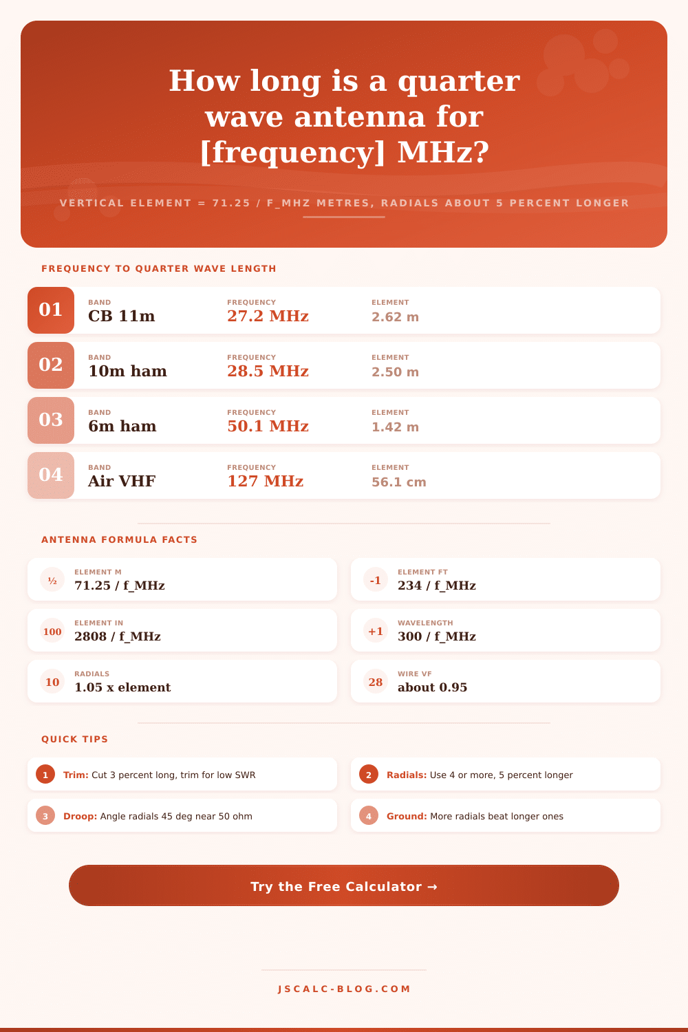
The key is the free-space wavelength. The equation is: Lambda=Speed of light/Frequency. In shorthand, C is constant, around 300 meters/second so that leaves us with lambda in meters = 300/frequency in MHz. One quarter of that is a perfect quarter wave. Or 75/freqency in MHz. But real wire isn’t perfect. There are end effects and there’s thickness of the wire which causes it to ring a little short. To include those facts of physics, we apply a velocity factor of approximately 0.95. That makes the quick calculation about 71.25 divided by the frequency in MHz, which gives you the element length in meters. On two-meters (146MHz) that’s about 19.2 inches, or 0.488 meters.
A shortcut that has been around for decades among radio hams: Divide 234 by the frequency in megahertz. The result is the element length in feet. When converted to the metric system, this is close to the 71.25 constant we found previously. The 234 constant already accounts for the end-effect shortening. If you want inches instead, just multiply all the way through for an answer of 2808 divided by the frequency in MHz. Enter your band information into the calculator above and let it do the math. As you can see, both methods lead to the same physical length. This means they both match each other. This is a nice sanity check prior to cutting anything since it assures us calculation was accurate.
To account for this difference (how much less than the textbook quarter wave that real elements actualy are), we have what’s called the velocity factor. For example, bare thin copper wire would be about 0.95 because there isn’t a lot of impedance from the wire insulation slowing down the wave. Hookup wire with insulation runs a little bit higher, at maybe 0.96. Thicker conductors like large-diameter whips or tubing run closer to 0.94 or even lower. Larger diameter means more capacitance at the end. With the tool, you can choose a type of conductor which presets the velocity factor logically, or you could put in your own number by hand. If you don’t know, the conservative default is 0.95, and the trimming process below will adjust for any slight mistakes.
Feed Impedance and Ground Plane set the pattern; but half the story is the vertical element. We include a.05 to show that we are looking at a radial length. The number of radials has more impact on efficiency than many newbies would imagine. How many do you need? You need a functional minimum of three radials. Classic ground-plane baseline is four. Eight to sixteen noticeably improve performance and reduce ground loss. If you have a four-radial horizontal plane, you feed with something like 36 ohms, a bit of a mismatch to your 50-ohm coax. Lowering those four radials down to approximately 45 degrees increases feed impedance towards 50 ohms and in some cases eliminates the need for an additional matching network. This one little geometry trick is one of the most valuable adjustments when building a vertical because it makes connecting the feed line so much easier.
Enter the center frequency into the calculator or choose one of the supplied band presets. You’ll need to determine what material(s) you’re using for the elements so select a conductor type to apply the correct velocity factor. Next you should choose the radial length factor along with number of radials to achieve your desired antenna traits. Finally, select if you’d like imperial or metric displayed first and the resulting four cards will provide the quarter-wave element in metric and in feet/inches, the full wavelength, and finally the length of each radial. If you wish to see how the values break down it’s there, too. The reference tables even allow you to jump between CB (at 27 MHz) and WiFi (2.4 GHz) without having to re-calculate everything yourself. This makes the process repeatable with consistent results across different frequencies.
Performance depends on the environment so there’s no formula that covers it all: The near-by metal, how high it’s mounted above the ground, the feed line and even the mast will all affect resonance by a bit. So just calculate it to be three percent overlong to start with and the go-to trick is mount it where you want it to live, then watch it on an antenna analyzer (or SWR meter) and cut it back a few millimeters at a time until it’s perfect. You’ll know when you get there. At low frequencies below 30 MHz, you’ve got centimeters of wiggle room. Above 400 MHz, every five millimeters will move the SWR noticeably. So take it slow so you don’t accidentally cut yourself short! It is better to start long and tune it down rather than trusting the calculator’s number; you could of always cut more off, but you can never put more back on.
Why? Simply put: Quarter-wave monopoles are small. They send signals in all directions along the horizontal plane. They are also easy to connect to a power source. That’s why they’re everywhere. For example, mobile whips on vehicles rely on the vehicle body as their ground plane, it couldn’t be easier. Ground planes for base stations do a great job covering 70-centimeter and two-meter repeaters. The same quarter-wave idea underlies CB whips, GMRS radios, marine VHF antennas, and even those fancy 915 MHz LoRa nodes. The design scales perfectly across frequency ranges; there is one calculator that covers the entire range of use cases. If you’re a boater who needs to replace the marine whip, or if you’re a newbie ham trying to cut your first two-meter antenna, you’ll get trusted length in seconds and see how each number comes out.