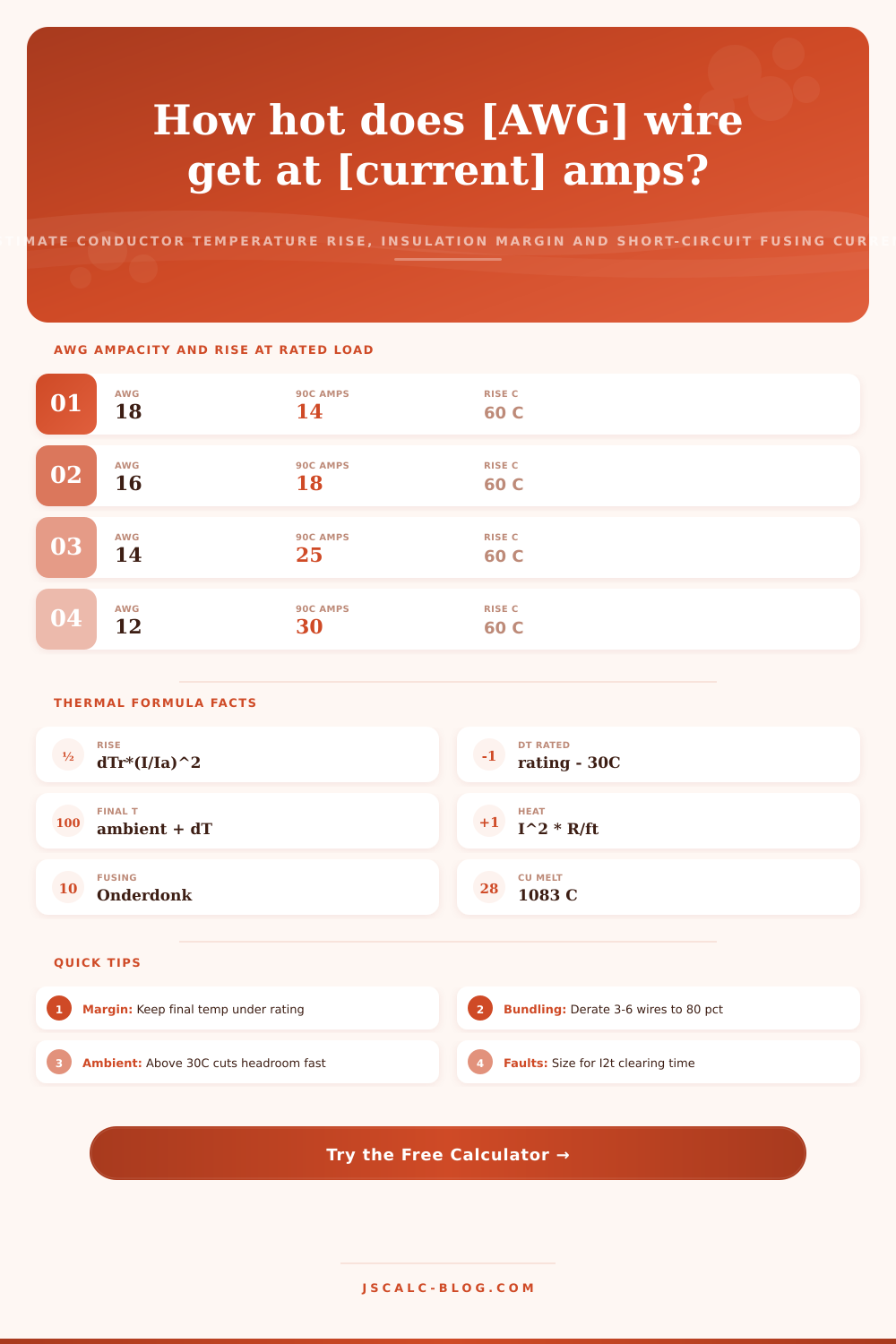
Wire Temperature Rise Calculator
Estimate how hot a current-carrying conductor gets using the temperature rise model delta T = delta T rated times the square of load current over ampacity. Get the final conductor temperature, how much of the insulation rating is used, the I squared R heat generated per foot, and the maximum short-circuit fusing current a copper wire survives from the Onderdonk equation.
📌Real Wiring Scenario Presets
🔌Conductor and Load Inputs
Sets ampacity, circular mils and resistance per foot.
The real continuous current the wire carries.
Maximum temperature the insulation tolerates.
Surrounding air temperature around the run.
Aluminum carries about 78 percent of copper ampacity.
Applies a bundling derate to effective ampacity.
Used for total I squared R heat over the run.
Breaker or fuse clearing time for the fusing check.
🔢Thermal Formula Snapshot
📊AWG Ampacity, Area and Resistance Grid
| AWG | Area (cmil) | Cu Ampacity 90C | Rise C at Rated | Cu Ohms / 1000 ft | Al Ampacity 90C |
|---|---|---|---|---|---|
| 18 | 1620 | 14 A | 60 C | 6.385 | -- |
| 16 | 2580 | 18 A | 60 C | 4.016 | -- |
| 14 | 4110 | 25 A | 60 C | 2.525 | -- |
| 12 | 6530 | 30 A | 60 C | 1.588 | 25 A |
| 10 | 10380 | 40 A | 60 C | 0.999 | 35 A |
| 8 | 16510 | 55 A | 60 C | 0.628 | 45 A |
| 6 | 26240 | 75 A | 60 C | 0.395 | 60 A |
| 4 | 41740 | 95 A | 60 C | 0.249 | 75 A |
| 2 | 66360 | 130 A | 60 C | 0.156 | 100 A |
| 1/0 | 105600 | 170 A | 60 C | 0.098 | 135 A |
| 2/0 | 133100 | 195 A | 60 C | 0.078 | 150 A |
| 4/0 | 211600 | 260 A | 60 C | 0.049 | 205 A |
🌡Load Fraction to Temperature Rise
| Load I / Ampacity | Rise Factor (I/Ia)^2 | Rise on 90C Wire | Final at 30C Ambient |
|---|---|---|---|
| 25 percent | 0.0625 | 3.8 C | 33.8 C |
| 40 percent | 0.16 | 9.6 C | 39.6 C |
| 50 percent | 0.25 | 15 C | 45 C |
| 63 percent | 0.40 | 24 C | 54 C |
| 71 percent | 0.50 | 30 C | 60 C |
| 80 percent | 0.64 | 38.4 C | 68.4 C |
| 90 percent | 0.81 | 48.6 C | 78.6 C |
| 100 percent | 1.00 | 60 C | 90 C |
🔥Insulation Rating and Reference Rise
| Rating | Typical Types | delta T Rated (rating - 30C) | Common Use |
|---|---|---|---|
| 60 C | TW, UF | 30 C | Older residential branch |
| 75 C | THW, RHW, USE | 45 C | Wet locations, feeders |
| 90 C | THHN, XHHW-2 | 60 C | Modern dry conductor runs |
| 105 C | Appliance wire | 75 C | Fixtures, luminaires |
| 150 C | Silicone, PTFE | 120 C | High-heat industrial |
| 200 C | Fiberglass, MG | 170 C | Furnace and oven leads |
⚡Copper Fusing Current by Fault Time
| AWG | Area (cmil) | Fusing at 1 s | Fusing at 0.1 s | Fusing at 0.01 s |
|---|---|---|---|---|
| 14 | 4110 | 0.83 kA | 2.6 kA | 8.3 kA |
| 12 | 6530 | 1.3 kA | 4.2 kA | 13.2 kA |
| 10 | 10380 | 2.1 kA | 6.6 kA | 21 kA |
| 8 | 16510 | 3.3 kA | 10.5 kA | 33 kA |
| 6 | 26240 | 5.3 kA | 16.7 kA | 53 kA |
| 4 | 41740 | 8.4 kA | 26.6 kA | 84 kA |
| 2 | 66360 | 13.4 kA | 42 kA | 134 kA |
| 1/0 | 105600 | 21 kA | 67 kA | 213 kA |
⚙Formula Breakdown
💡Practical Thermal Tips
You may have noticed your wire nuts are warm when touched. Is that hot? What’s considered hot? Well, ampacity tables is binary… They provide a yes/no answer as to whether something passes or fails. They don’t inform you of any remaining margin of safety against excessive heat.
Even if two wires is within code by being at 50% their rated current, this doesn’t make them behave identically. Wires operating near capacity (e.g., 90%) differ significant from those running at half-charge. It’s the rate of accumulation of heat under varying loads that makes an installation “hot” versus merely complying with code.
Why Wires Get Hot
Heating is proportional to the square of current; therefore the physics is easy but unforgiving. Doubling the load quadruples amount of heat created per foot of wire. It will continue to warm up until it lose as much heat as it produces to surrounding air.
This ampacity are the current at which a given wire reaches the limits of its insulation in a normal thirty-degree Celsius room. Junior electricians and many DIY-ers fail here because they believe a wire rated for 90 degrees Celsius remains cool as long as insulation can handle the heat. What’s going on in the wall or conduit at any time determine the real temperature.
To do this the calculators take the real world load and divide it against effective ampacity of the wiring configuration. So for example, if you bundle four or six conductors together in a conduit, you must derate their capacity because they trap each other’s heat. Additionally, aluminum heats up quicker then copper at the same amount of amperage. Aluminum carries approximately seventy-eight percent as much current as copper of equal size. This means aluminum will be hotter under the same load.
The calculator consider this difference in materials as a first step and then uses square law to calculate how hot it gets. Because it’s a squared relationship, there’s a lot of room to get it wrong. When running more than one conductor in a conduit (or even when bundling them), those conductors will trap each other’s heat, so you have to derate that bundle of four or six conductor. That twenty percent loss in effective ampacity may not seem like much, but that squaring effect increases the load fraction and realy jacks up the temperature rise. On paper, you’re thinking you’re still well within limits. But in reality, your wire is getting closer to its melting point at a much faster rate.
The tool calculate the final temperature with ambient air surrounding the run. The load doesn’t stand alone; it’s also dependent on the ambient temperature. At full-load, a cool-basement wire has lots of headroom. The same wire in a sweltering hot-summer attic start with zero margin because the hot air uses up all the allowed temperature increase. If your insulation is rated for 90 C and the ambient is now fifty degrees C… you have but forty degrees of rise before you start degrading the plastic. You can enter the actual ambient temperature into the calc, instead of relying on standard assumptions which might not apply to your site.
This all comes down to insulation ratings. Sixty degree Celsius (C) wire, what you typically find in older houses, give very little room for error. Moddern XHHW and THHN wire rates to ninety degrees (C), so they can be bundled together or exposed to higher ambient temperatures with a bigger margin of safety. The insulation rating determines the temperature difference used to calculate everything else. If you don’t know your insulation rating, your temperature estimates wouldn’t of come from anywhere but guesswork.
Fault current (the output of the fusing) covers the short circuit case, when huge amounts of current flow through for just a second or two until your breaker trips. This is based off the Onderdonk equation. It takes into account the thermal mass of the copper and how fast it reaches its melting temperature, which is about one thousand eighty-three degrees Celsius. Large feeder wires has enough thermal mass to withstand much larger fault currents, whereas small gauge wire will melt immediately under those conditions. It links temporary fault energy with steady state heating.
To see what happens when variables go up or down, they have ten preset scenarios that allow you to visualize common uses like dryer lines or kitchen circuits without having to enter in any data yourself. It’s amazing how fast things swing into the danger zone once the variables change! Try testing your assumptions of what gets hot and what doesn’t.
Remember the reduction factors on those bundled runs and keep that final temperature far under the insulation rating. You’ll be managing the heat instead of just hoping it doesn’t become a problem. As a result, your wires will last longer and your system will remain safer.