Speaker Wire Gauge Calculator
Enter your one-way run length and speaker impedance and this tool recommends the correct AWG, keeping total round-trip wire resistance under 5 percent of the speaker impedance so level loss stays under 0.5 dB and damping factor is preserved. It also reports the actual wire resistance, power and dB loss, and the damping factor seen at the speaker.
🎯Real Install Presets
🔊Speaker and Run Inputs
Nominal driver impedance; 4 ohm loads need heavier wire.
Distance from amplifier to one speaker, not the round trip.
The calculator doubles this for the out-and-back path.
Max round-trip Rwire allowed as a percent of impedance.
CCA has about 1.5x the resistance of pure copper.
Used to estimate watts lost as heat in the cable.
Solid-state amps are near 0; used for damping factor.
In-wall runs must use CL2 or CL3 fire-rated jacketing.
📐Formula Snapshot
📋Run Length vs Recommended AWG (5% rule)
| One-Way Run | 4 ohm | 6 ohm | 8 ohm | 16 ohm | Max Rwire 8 ohm |
|---|---|---|---|---|---|
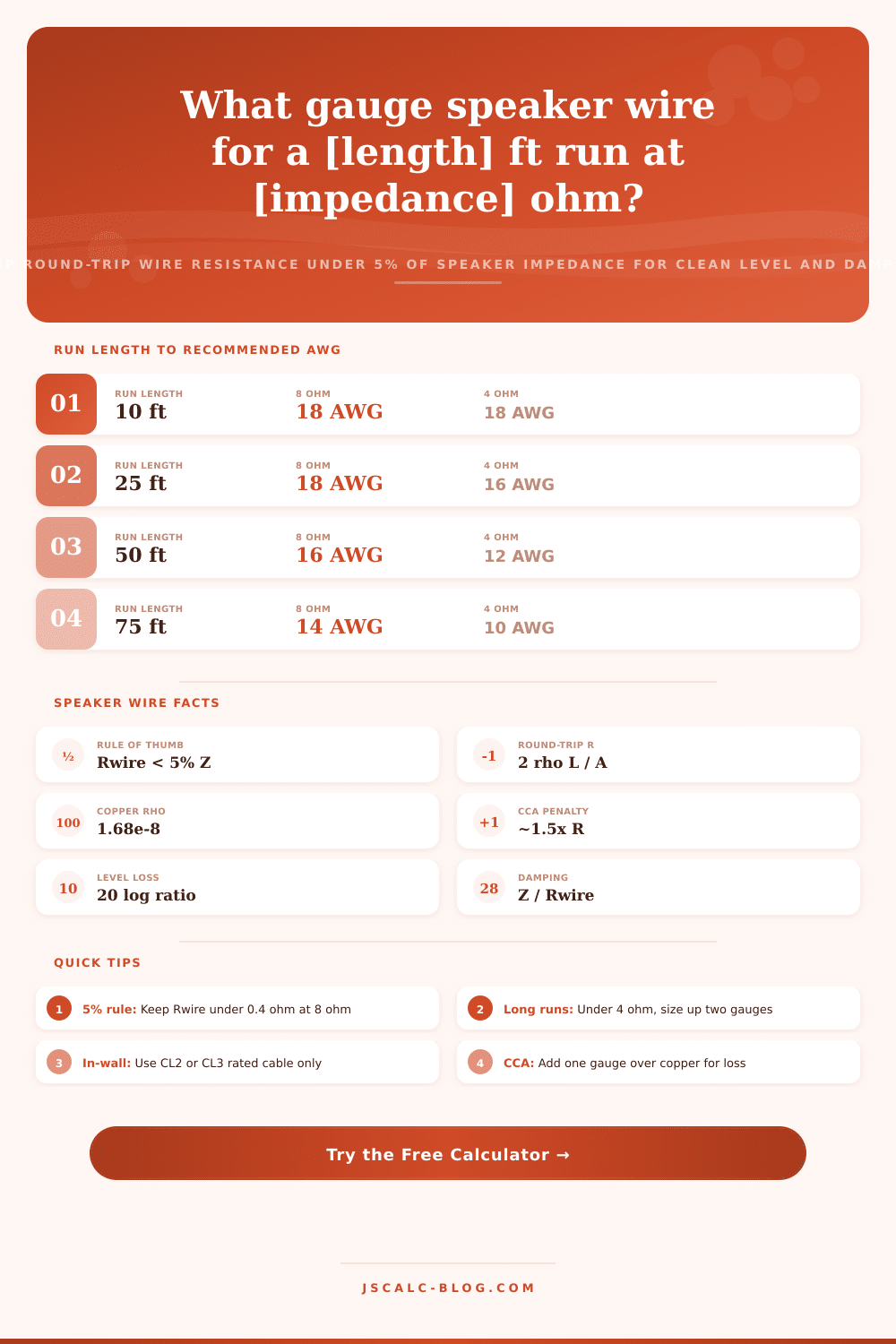
| 10 ft | 18 AWG | 18 AWG | 18 AWG | 18 AWG | 0.40 ohm |
| 25 ft | 16 AWG | 16 AWG | 18 AWG | 18 AWG | 0.40 ohm |
| 50 ft | 12 AWG | 14 AWG | 16 AWG | 18 AWG | 0.40 ohm |
| 75 ft | 10 AWG | 12 AWG | 14 AWG | 16 AWG | 0.40 ohm |
| 100 ft | 10 AWG | 10 AWG | 12 AWG | 16 AWG | 0.40 ohm |
| 125 ft | 8 AWG | 10 AWG | 12 AWG | 14 AWG | 0.40 ohm |
| 150 ft | 8 AWG | 10 AWG | 10 AWG | 14 AWG | 0.40 ohm |
| 200 ft | 6 AWG | 8 AWG | 10 AWG | 12 AWG | 0.40 ohm |
🧵AWG Resistance and Diameter (copper)
| AWG | Diameter (mm) | Area (mm²) | Resistance ohm / 1000 ft | Resistance ohm / km |
|---|---|---|---|---|
| 18 AWG | 1.024 | 0.823 | 6.222 | 20.41 |
| 16 AWG | 1.291 | 1.309 | 3.913 | 12.84 |
| 14 AWG | 1.628 | 2.081 | 2.461 | 8.07 |
| 12 AWG | 2.053 | 3.309 | 1.548 | 5.08 |
| 10 AWG | 2.588 | 5.261 | 0.973 | 3.19 |
| 8 AWG | 3.264 | 8.367 | 0.612 | 2.01 |
| 6 AWG | 4.115 | 13.30 | 0.385 | 1.26 |
📊Wire Resistance as Percent of 8 ohm
| Round-Trip Rwire | % of 8 ohm | Level Loss (dB) | Power Lost | Verdict |
|---|---|---|---|---|
| 0.08 ohm | 1% | 0.09 dB | 1.0% | Excellent |
| 0.16 ohm | 2% | 0.17 dB | 2.0% | Audiophile |
| 0.24 ohm | 3% | 0.26 dB | 2.9% | Very good |
| 0.40 ohm | 5% | 0.42 dB | 4.8% | Recommended max |
| 0.64 ohm | 8% | 0.67 dB | 7.4% | Borderline |
| 0.80 ohm | 10% | 0.83 dB | 9.1% | Background only |
⚙Formula Breakdown
💡Speaker Wire Sizing Tips
Selecting speaker wire should be easy, but the thick cables you see on the racks at the electronics store cost more and are said to make your system sound better. In fact it’s a matter of just two numbers you have: How far is the speaker from the amp? And what is the speaker’s nominal impedance? Enter them here, and this Speaker Wire Gauge Calculator recommends a good AWG size based off those two pieces of data. It also walks you through the how and why. This helps you understand and believe the answer rather than blindly assuming.
The point is not maximum-gauge wire. Rather it’s the lightest (and cheapest) gauge that avoids audible signal loss. Audio engineers have a rock-solid rule of thumb: the combined round-trip resistance of your speaker cable must be no more than 5 percent of the speaker’s impedance. That means that if you’re beneath that number, the drop in sound pressure level and other effects on the amp stay under the limits of what most listeners can hear. To put it another way: there’s a hard cap on how much wire resistance you can have and still not cause problems.
How to Choose the Right Speaker Wire Gauge
The formula goes like this: (loss %/100) x speaker impedance = max wire resistance. So with an 8 ohm speaker, the ceiling is 0.40 ohms; with a 4 ohm speaker, the ceiling drops to 0.20 ohms. Why? Because low-impedance speakers require thicker wire to keep signal loss and resistance under control, thus requiring bigger-wire runs at least within the amp-to-speaker path. A lot of folks forget this when shopping for thinner wire for their higher-power system components. You can’t push as much power through a lower-impedance driver without causing too much heat buildup in the speaker. This requires thicker wires, at least for the path from the amp to the speaker. A lot of folks forget this when shopping for thinner wire for they higher-power system components.
The bigger the wire diameter, the less resistance it has; the longer the wire is, the more resistance it has. So we consider both those things in the calculation, using a common conductor equation. Resistance = (resistivity * Length) / (Conductor Area), or round trip = 2 x (resistivity * Length)/Conductor Area. That’s why there’s a two in there, since current comes back into the system on the opposite conductor. So it has to travel twice as far as you think when measuring distance. The resistivity of copper is 1.68 times ten to the minus eight ohm-meters. The gauge number is directly related to area. Then the tool will check through each gauge, starting with thinnest and stopping at the first where your resistance allowance is not exceeded.
There are always four numbers for every calc. The first one is the recommended gauge. This is called the recommended gauge. It is the lowest cost, smallest AWG cable that delivers amount of loss you specified at the distance you provided. Next is the round trip resistance card which will show you exactly how many ohms that cable has. Then it will display what percent of the speaker impedance that is, showing how much room you have left before hitting the 5% maximum.
Next is the power and level loss card which will display in decibels just how much signal is lost to reach the driver. Also it will display number of watts from the amp that are being converted into heat energy in the wire. And lastly, there’s the damping factor card which shows the ratio between the speaker’s own impedance and the total source resistance in series with the speaker. This will tell you how tightly the amp is controlling the cone with the wire installed. It is a little tidbit, but it makes a difference with tightness for bass.
If the speakers differ in impedance, then two similarly long runs might need differing wire gauges. Allowable resistance is directly proportional to impedance. In other words, an 8 ohm speaker can handle twice as much cable resistance than a 4 ohm one. For example, 16 gauge can handle a 50 foot run and work fine on an 8 ohm bookshelf. But that same length run would have too much resistance for a more demanding 4 ohm tower, which needs 12 gauge wire or less to stay within its tighter 0.20 ohm limit. The chart on the page spells out that and more for several load scenarios. That way you can double-check your calculation against a chart.
Back Don’t assume that speaker wire is all solid copper. A lot of budget speaker wire is made from copper-clad aluminum, known as CCA. It’s got a thin coating of copper over an aluminum core. Because aluminum doesn’t conduct as well as copper, a CCA cable will have approximately 1.5 times the resistance of a pure copper cable of equal gauge. This penalty gets applied automaticly by the calculator if you choose to specify the conductor material. In practice, if you purchase CCA, you should increase the wire size by about one gauge step. You should of this compared to what you would use for a pure copper cable of the same length. Or the tool can simply choose the right larger gauge for you.
A damping factor is a way to express the ability of an amp to begin and halt movement of a woofer quickly. That’s dependent upon the overall amount of resistance connected in series with the driver. The formula is the resistance of the driver (impedance) divided by the combination of the wire resistance plus the output impedance of the amplifier. Today’s solid state amps has their output impedance rated in a few hundredths of an ohm. So for long runs, the cable will typically be the dominant term.
Low resistance in the wire accomplishes two things. First, it maintains higher volume levels. Second, it ensures the damping factor is high enough to keep the bass tight rather than loose and boomy. The calculator will report the damping factor as a result which lets you track its decrease as gauge gets smaller or length of run increases.
In the real world, those numbers stand up if you develop a couple of habits. Size all the cable to the longest run in a pair of speakers and make sure both channels is the same. If a result falls on the boundary, round up (not down) because corrosion and connectors add resistance over time. If the run is marked “in-wall” the tool will flag fire code, which requires jacketed cable with ratings of at least CL2 or CL3 if routed inside a ceiling or wall. There are presets for patio, outdoor, subwoofer, in-ceiling, tower and bookshelf runs to get you going quickly. Pick a preset that approximates your setup and then tweak the material, length and impedance to match your gear. Then tighten the loss threshold for critical listening or loosen it up for background zones where nobody notices a small drop. As you play around, see how the gauge, resistance, damping factor and decibel loss interrelate. Once wired, do it right the first time, confidently.