Wire Ampacity Calculator
Enter a known conductor gauge and its install conditions to find the derated ampacity of the wire. The tool starts from the AWG ampacity table for your insulation temperature rating, corrects for ambient heat, adjusts for the number of bundled current-carrying conductors, and reports the 80 percent continuous load limit.
🎯Real-World Wiring Presets
📝Conductor and Install Conditions
The known gauge you are checking the capacity of.
Aluminum carries roughly 78 percent of copper.
Selects which ampacity column to start from.
Air temperature around the wire, not the load.
Bundled or in the same raceway or cable.
Free air runs cooler; note terminal limits still apply.
Continuous loads use the 80 percent rule.
Controls the displayed amp precision.
🔢Calculation Snapshot
📋Copper Ampacity by AWG and Insulation Column
| AWG | Cu 60C | Cu 75C | Cu 90C | Al 75C | Typical Use |
|---|---|---|---|---|---|
| 14 | 15 A | 20 A | 25 A | - | Lighting, 15A |
| 12 | 20 A | 25 A | 30 A | 20 A | Receptacles, 20A |
| 10 | 30 A | 35 A | 40 A | 30 A | Dryer, water heater |
| 8 | 40 A | 50 A | 55 A | 40 A | Range, 40A feeder |
| 6 | 55 A | 65 A | 75 A | 50 A | 50A range, subfeed |
| 4 | 70 A | 85 A | 95 A | 65 A | Subpanel feeder |
| 2 | 95 A | 115 A | 130 A | 90 A | 100A feeder |
| 1/0 | 125 A | 150 A | 170 A | 120 A | 150A service leg |
| 2/0 | 145 A | 175 A | 195 A | 135 A | Large subpanel |
| 4/0 | 195 A | 230 A | 260 A | 180 A | 200A service |
🌡Ambient Temperature Correction Factors
| Ambient C | 60C Wire | 75C Wire | 90C Wire | Effect |
|---|---|---|---|---|
| 21-25 | 1.08 | 1.05 | 1.04 | Slight boost |
| 26-30 | 1.00 | 1.00 | 1.00 | Base rating |
| 31-35 | 0.91 | 0.94 | 0.96 | Small derate |
| 36-40 | 0.82 | 0.88 | 0.91 | Warm space |
| 41-45 | 0.71 | 0.82 | 0.87 | Noticeable loss |
| 46-50 | 0.58 | 0.75 | 0.82 | Hot attic |
| 51-55 | 0.41 | 0.67 | 0.76 | Severe derate |
📊Conductor Bundling Adjustment
| Current-Carrying Conductors | Adjustment Factor | Example |
|---|---|---|
| 1 to 3 | 1.00 (100%) | Standard branch circuit |
| 4 to 6 | 0.80 (80%) | Two shared circuits |
| 7 to 9 | 0.70 (70%) | Crowded raceway |
| 10 to 20 | 0.50 (50%) | Full conduit run |
⚙Formula Breakdown
💡Ampacity Sizing Tips
Ever wonder how much current you can push through your wiring? All electricians, and some serious do-it-yourselfers, has asked themselves that question at one time or another. That’s where a wire ampacity calculator comes into play.
What’s ampacity? It’s the maximum amount of current that a conductor can pass before heating insulation past the rated safe amount. The table values do not tell whole story. Actual capacity is based off the rating of the insulation itself, ambient air temperature, and number of other conductors in the same raceway. This calculator begins with a given gauge size and takes you step by step through all corrections to arrive at your final derated ampacity and the critical 80 percent continuous load limit.
How a Wire Ampacity Calculator Works
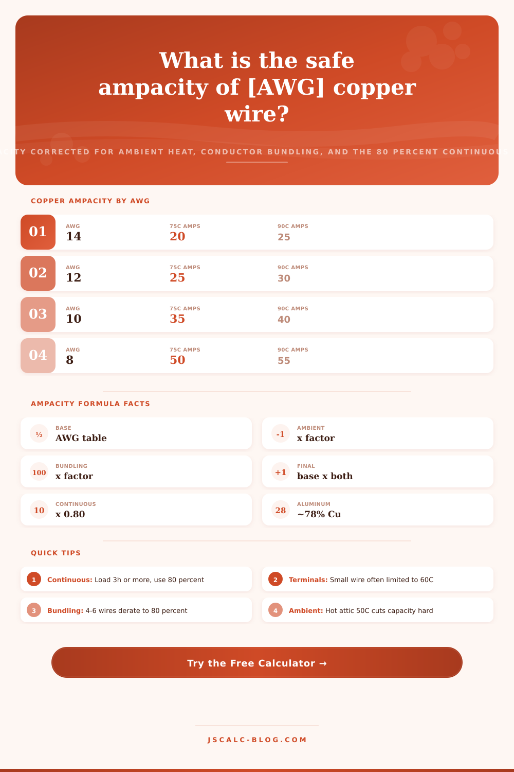
There’s a base ampacity associated with every conductor size based on the temperature of the conductor metal and its insulation. Because the same-sized aluminum conductor carry about 78 percent as much current as copper, aluminum feeders tend to be larger. Wires rated for hotter temperatures has a higher base value: they can operate at higher temperatures before failing. In this case, a 12 AWG copper conductor is rated for 20 amps if the conductor temperature doesn’t exceed 60C; it’s rated for 30 amps if that temperature doesn’t go beyond 90C.
The initial choice is selecting the proper column. The calculator above lets you select the rating that matches the jacket so you start from the right place before making corrections.
The published ampacity assumes an ambient temperature around 30C, or 86F. If you have a wire running through a hot boiler room or attic, then surrounding air is warmer. Because the conductor can’t easily shed heat, its safe capacity decreases. This is where the multiplier comes into play. With a 90C conductor and ambient of 40C, the factor approaches 0.91. With ambient of 50C, that factor drops to ~0.82. Lower rated insulation suffers worse in heat. The tool automatically computes and uses proper factor for the column you select, displaying the actual reduced capacity rather than the optimistic value from the tables. People make mistake here by assuming the wire rating is fixed where in fact it is environmental.
It’s cumulative. Ampacity also depends on how many other current-carrying conductors you bundle into a conduit. Each will warm others. Reduce the ampacity of all conductor. Four to six is 80 percent. Seven to nine drop to 70 percent. Ten to 20 is 50 percent. And this is just for current-carrying conductors. Usually, this means a neutral carrying only the unbalanced current is not very important. That’s why it says “current-carrying” above.
The ambient factor and the bundling adjustment are both multipliers that stack together, which can catch someone off guard if they don’t recall it when they go into a packed raceway. The calculator accounts for these overlapping penalties: You’ll see what the actual capacity of wire is under these circumstances. With all of the parts in place, the formula becomes simple. The bundle adjustment x the ambient correction x the base table value = final ampacity. So taking our example of a 6-conductor bundle (copper) of 12 AWG wire, rated to 90C in an ambient temperature of 40C yields approximately 21.8 amps. That figure apply only to this specific situation. As you might imagine, it’s frequently much lower then what you’ll find if you just look on a chart. That is why it is important to run the numbers.
There is one last limitation on daily circuit design. Continuous loads run at full power for three hours or longer. Electric heating or lighting in a store are an example. In this case, both the breaker and the conductor can only be loaded to 80 percent of their ratings. It’s a safety factor against accumulated heat buildup at the terminals. Hence, you need 8 AWG wire on a 40 amp range circuit instead of 10 AWG. The tool displays this continuous loading next to final derated ampacity so that you’re not just guessing when sizing your breaker but doing it confidently.
Insulation is often rated 90C but the terminals to which it’s attached aren’t. Most breakers and lugs is listed for 60C on smaller wires and 75C on larger ones. They use higher starting point in the 90C column to calculate derating figures. But temperature rating of the terminal will cap actual current flow. Overheating of connections is a frequent panel failure reason, don’t ignore it. Reading down table is the way to ensure both wire and terminations stay safely within their limits.
That’s one reason I wanted to show you how the workflow works quickly. Just pick a preset and load one of the standard branch circuits. Watch numbers come up for a baseline. Then go to an example with bundled conductors. Watch as derating is applied. Next select a hot attic service run. Watch as ambient heat takes large part of capacity. All results appear instantly, with the base, temperature adjusted, and final numbers shown side-by-side so you can see how the calculations combine. Ambient plus bundling minus base equals the real safe current carrying capacity of a known gauge.
So now you don’t have to flip pages looking through tables anymore. Enter what kind of conductor you’re using. Describe where it is. Read actual safe current in seconds. What’s on the spool isn’t the full story.