VSWR Calculator
Find the voltage standing wave ratio three ways: from a complex load impedance on a known line, from a reflection coefficient magnitude, or straight from a VSWR value. The tool returns VSWR as a clean ratio like 1.50:1 plus the reflection coefficient, return loss in dB, mismatch loss, and the percent of power reflected back to the source.
📡Choose an Input Method
🎯Real Antenna and Line Presets
📝Match Inputs
Characteristic impedance of the feedline, usually 50 or 75.
Real part of the antenna or load impedance.
Imaginary part; positive is inductive, negative capacitive.
Magnitude only, between 0 (matched) and 1 (full reflect).
Enter the ratio number; 1 is a perfect match.
Incident power, used to report watts reflected and delivered.
Controls rounding on every result card and row.
🔢Formula Snapshot
📋Resistive Load to VSWR on 50 Ohm Line
| Load R (X = 0) | |Gamma| | VSWR | Match Quality |
|---|---|---|---|
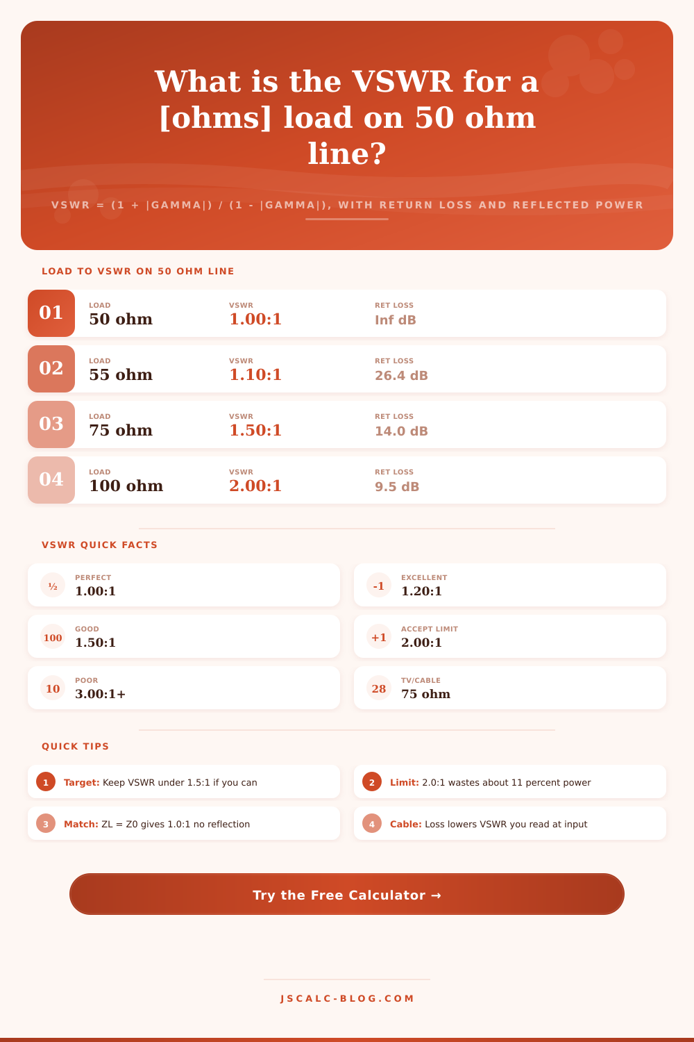
| 50 ohm | 0.000 | 1.00:1 | Perfect |
| 55 ohm | 0.048 | 1.10:1 | Excellent |
| 60 ohm | 0.091 | 1.20:1 | Excellent |
| 75 ohm | 0.200 | 1.50:1 | Good |
| 100 ohm | 0.333 | 2.00:1 | Accept limit |
| 25 ohm | 0.333 | 2.00:1 | Accept limit |
| 150 ohm | 0.500 | 3.00:1 | Poor |
| 200 ohm | 0.600 | 4.00:1 | Poor |
📊VSWR to Loss and Reflected Power
| VSWR | |Gamma| | Return Loss | Reflected Power | Mismatch Loss |
|---|---|---|---|---|
| 1.00:1 | 0.000 | Infinite | 0.0 % | 0.00 dB |
| 1.10:1 | 0.048 | 26.4 dB | 0.2 % | 0.01 dB |
| 1.20:1 | 0.091 | 20.8 dB | 0.8 % | 0.04 dB |
| 1.50:1 | 0.200 | 14.0 dB | 4.0 % | 0.18 dB |
| 2.00:1 | 0.333 | 9.5 dB | 11.1 % | 0.51 dB |
| 3.00:1 | 0.500 | 6.0 dB | 25.0 % | 1.25 dB |
| 4.00:1 | 0.600 | 4.4 dB | 36.0 % | 1.94 dB |
| 5.00:1 | 0.667 | 3.5 dB | 44.4 % | 2.55 dB |
| 10.0:1 | 0.818 | 1.7 dB | 66.9 % | 4.81 dB |
📡Typical VSWR Acceptance Limits by Use
| Application | Line Z0 | Target VSWR | Max VSWR | Notes |
|---|---|---|---|---|
| Ham HF transceiver | 50 ohm | 1.5:1 | 2.0:1 | Foldback above 2:1 |
| VHF/UHF repeater | 50 ohm | 1.2:1 | 1.5:1 | Duplexer sensitive |
| Cellular base station | 50 ohm | 1.3:1 | 1.5:1 | Alarms near 1.5:1 |
| Broadcast FM/TV | 50 ohm | 1.1:1 | 1.2:1 | High power care |
| Cable TV distribution | 75 ohm | 1.2:1 | 1.4:1 | Return path clean |
| Lab bench / VNA | 50 ohm | 1.05:1 | 1.1:1 | Precision loads |
| Mobile whip antenna | 50 ohm | 1.5:1 | 2.0:1 | Retune per band |
🗃Complex Load Comparison Grid (50 Ohm Line)
| Load R | Load X | |Gamma| | VSWR | Return Loss | Reflected |
|---|---|---|---|---|---|
| 50 ohm | 0 | 0.000 | 1.00:1 | Infinite | 0.0 % |
| 50 ohm | +25 | 0.243 | 1.64:1 | 12.3 dB | 5.9 % |
| 75 ohm | 0 | 0.200 | 1.50:1 | 14.0 dB | 4.0 % |
| 36 ohm | +20 | 0.290 | 1.82:1 | 10.8 dB | 8.4 % |
| 25 ohm | -40 | 0.585 | 3.82:1 | 4.7 dB | 34.2 % |
| 100 ohm | 0 | 0.333 | 2.00:1 | 9.5 dB | 11.1 % |
| 73 ohm | +43 | 0.371 | 2.18:1 | 8.6 dB | 13.8 % |
| 50 ohm | -50 | 0.447 | 2.62:1 | 7.0 dB | 20.0 % |
| 300 ohm | 0 | 0.714 | 6.00:1 | 2.9 dB | 51.0 % |
| 16.7 ohm | 0 | 0.500 | 3.00:1 | 6.0 dB | 25.0 % |
⚙Formula Breakdown
💡VSWR Field Tips
For an RF engineer, single number they reach for first when checking antenna match is voltage standing wave ratio. That’s because it measures how much of the energy coming into antenna goes into the load and how much comes back to transmitter.
By using this VSWR calculator, you can find the voltage standing wave ratio in one of three ways, from a reflection coefficient, a complex impedance, or directly from a measurement. Then it’ll convert the number into reflected power, mismatch loss and return loss, which let you quickly see health of your system without having to do the math. Knowing what each means is the trick.
What is VSWR and How to Use a Calculator
If load on a transmission line is not a perfect match to it, some portion of the wave will reflect backwards. This creates a series of peaks and troughs in the cable as forward and reflected waves interacts. The greatest voltage peak relative to the smallest voltage trough is called VSWR. If there was a perfect match there would be no reflection at all, thus the voltage across transmission line would be flat and ratio would be 1.00:1. The greater the mis-match the higher the peaks and lower the valleys are.
Generally a reading of 1.5:1 is good. Before transmitters cut back on power to protect themselves two to one is usually the limit.
How does it do it? It is simple. The core formula takes into account the characteristic impedance (usually fifty ohms) of line versus your load impedance. Then it shows you fraction of wave that’s bounced back, or reflection coefficient, aka Gamma. So if we had a 75 ohm load on a fifty ohm line, then Gamma would be 0.2. Multiply by 100 and we get a VSWR of 1.5:1. Even though resistance isn’t necessarily pure, like a shortened whip has some capacitance, it still uses size of the complex number to give an accurrate reading. Most folks overlook this fact because they tend to only pay attention to resistance and forget about reactance. However, stray inductance or capacitance can drive VSWR up at same rate.
Knowing how to do it backwards can come in handy since field instruments typically display VSWR on a direct readout. The reverse formula returns a Gamma value from a given ratio (e.g., 2.0:1). In the case of a 2.0:1 VSWR, that’s equivalent to a Gamma of 0.333. That represents approximately eleven percent of power going back toward you.
The calculator spells it out quite nicely in the results panel. Not only does it show the wattage, but also corresponding percentage. It is easier to grasp amount of power being reflected when you see it alongside wattage. An 11% reflection with a hundred-watt forward signal means almost eleven watts of your power are heating up your feedline rather than getting sent out into space. Having that broken down by watts can be more convincing than just seeing a number by itself.
Another way to look at the same information is in return loss, which appears in decibels. Return loss represents relative strength of returned wave compared to forward wave. Thus higher the return loss, the better the match. For example, fourteen decibels of return loss corresponds to a Gamma of 0.2. Mismatch loss refers to amount of power that is reflected at the interface and therefore lost. At a VSWR of 2:1, mismatch loss is less than one-half decibel.
Newcomers often expect a two-to-one readout to be end of everything. It’s not. The problem arises as the VSWR goes much higher, such as to three or four, where reflected power increases dramatically and can cause serious heating in solid-state amplifiers. Antennas are not normally pure resistances at operating frequency; there is a bit of reactance involved as well, and that reactance make for a rapidly increasing reflection coefficient. A 36 ohm resistance plus 20 ohms of reactance may be your antenna load. The calculator allows for either sign of reactance, so it can model capacitive or inductive loads. Typically you’d cancel out the reactance first then tune the resistance to desired impedance of feedline, which is called tuning. Antenna element length is trimmed until resonance is achieved, then attention is paid to ultimate match point.
There are the reference tables on the page that specify typical limits for different kinds of applications such as broadcast stations and ham radios. For example, most transmitters can handle a comfortable 2.0:1. Cellular systems often require stricter matching with targets around 1.3:1. Lab gear expects nearly perfect loads. If you know how much tolerance your system has, it will tell you when match is sufficient or should of been adjusted. In most real-world situations, you don’t need a perfect 1.0:1. Just make sure you have reflected power low enough so your hardware operates well and stays cool.
The results of any calculations are presented in an easy-to-read summary of the match quality. It shows percent of power reflected, reflection coefficient, return loss, and the VSWR ratio. It also provides a status message indicating whether the match is poor, good, or excellent. These numbers provide a reliable indication of how well something is performing whether it’s a new repeater install you’re checking or homebrew antenna you’re trying to debug.
The name of the game is always the same: Get all that energy out of the transmitter and into the air where it belongs. By keeping your standing wave ratio low, you ensure that your signal goes where you want it. This prevents power from reflecting back off itself and heating up your cables instead.