Antenna Height for Line of Sight Calculator
Solve the mast height your radio link actually needs. Enter a target distance and the far antenna height, and this tool inverts the 4/3 earth horizon formula d = 4.12 (sqrt h1 + sqrt h2) to return the required near antenna height, each end radio horizon, an achievable distance check, and a suggested height that adds Fresnel and terrain margin.
📶Choose a Mode
📡Real Radio Link Presets
📝Link Inputs
The path length you need to cover end to end.
Applies to the target distance above.
Known height of the antenna at the other end.
Unit for far height and every reported height.
Refraction factor. 1.33 = 4/3 standard, 1.0 = true horizon.
Extra height for trees or ground rise, same unit as height.
Used for the mid-path Fresnel clearance estimate.
Controls rounding on every result card.
🔢Formula Snapshot
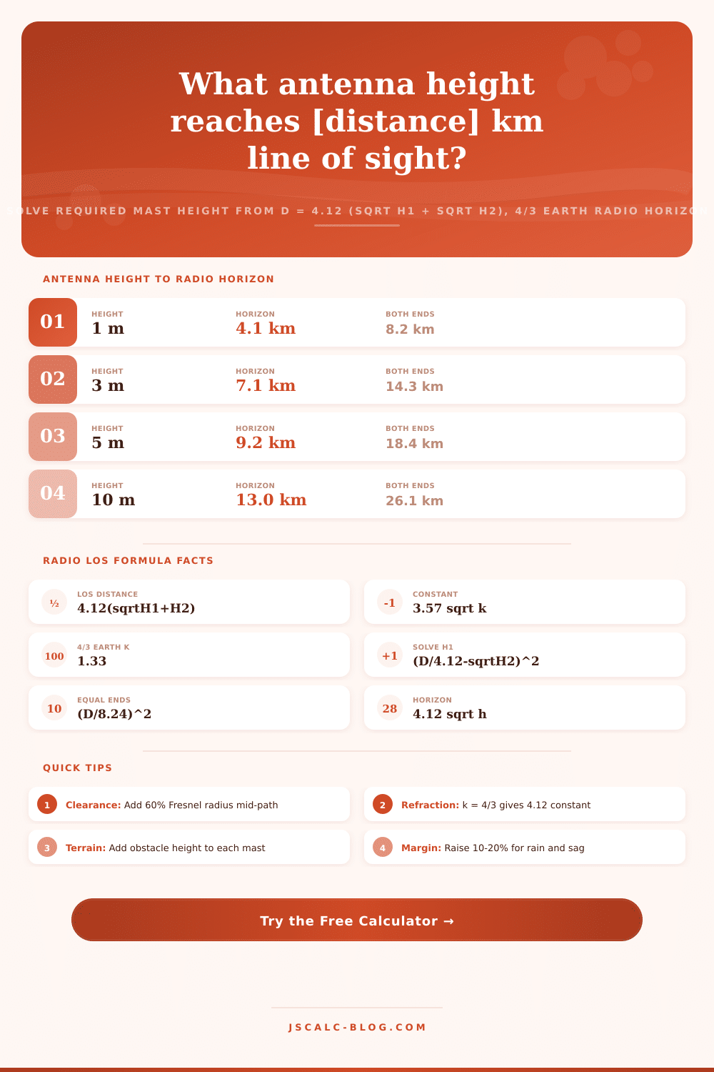
📋Antenna Height to Radio Horizon
| Antenna Height | Radio Horizon (4/3) | True Horizon (k=1) | Both Ends Equal |
|---|---|---|---|
| 1 m | 4.12 km | 3.57 km | 8.24 km |
| 3 m | 7.14 km | 6.18 km | 14.27 km |
| 5 m | 9.21 km | 7.98 km | 18.43 km |
| 10 m | 13.03 km | 11.29 km | 26.06 km |
| 15 m | 15.96 km | 13.83 km | 31.92 km |
| 20 m | 18.43 km | 15.97 km | 36.85 km |
| 30 m | 22.57 km | 19.55 km | 45.13 km |
| 50 m | 29.13 km | 25.24 km | 58.27 km |
| 100 m | 41.20 km | 35.70 km | 82.40 km |
| 150 m | 50.46 km | 43.72 km | 100.92 km |
📏Required Height for a Target Distance
| Target Distance | Far Height h2 | Required Near h1 | Equal Both Ends | Note |
|---|---|---|---|---|
| 5 km | 3 m | 0.02 m | 0.37 m | Handheld range |
| 10 km | 10 m | 1.16 m | 1.47 m | Short link |
| 15 km | 10 m | 4.99 m | 3.31 m | Rooftop pair |
| 20 km | 15 m | 3.85 m | 5.89 m | WISP hop |
| 30 km | 30 m | 7.14 m | 13.25 m | Tower pair |
| 40 km | 20 m | 32.44 m | 23.56 m | Long VHF |
| 50 km | 50 m | 19.87 m | 36.81 m | Backhaul |
| 60 km | 100 m | 19.85 m | 53.01 m | Ridge link |
📶Earth Curvature Factor k Effect
| k Factor | Condition | Constant 3.57 sqrt k | 10 m Horizon | Notes |
|---|---|---|---|---|
| 0.7 | Sub-refraction | 2.99 | 9.45 km | Ducting risk low |
| 1.0 | No refraction | 3.57 | 11.29 km | Geometric horizon |
| 1.33 | Standard 4/3 | 4.12 | 13.03 km | Typical design |
| 1.5 | Humid coastal | 4.37 | 13.82 km | Slightly farther |
| 2.0 | Strong refraction | 5.05 | 15.97 km | Warm marine air |
| 3.0 | Super-refraction | 6.18 | 19.55 km | Ducting likely |
📡Radio Link Design Comparison Grid
| Link Type | Distance | Far Height | Frequency | Required Near h1 | With Margin |
|---|---|---|---|---|---|
| Farm Wi-Fi | 10 km | 10 m | 5.8 GHz | 1.16 m | ~3 m |
| Village WISP | 20 km | 15 m | 5.8 GHz | 3.85 m | ~7 m |
| Ham 2m SSB | 40 km | 15 m | 0.144 GHz | 39.5 m | ~44 m |
| Tower to Tower | 30 km | 30 m | 5.8 GHz | 7.14 m | ~12 m |
| Boat to Shore | 15 km | 20 m | 0.156 GHz | 1.31 m | ~4 m |
| Farm CCTV | 5 km | 6 m | 5.8 GHz | 0.09 m | ~2 m |
| Microwave Backhaul | 50 km | 50 m | 6 GHz | 19.9 m | ~30 m |
| LoRa Gateway | 25 km | 12 m | 0.868 GHz | 12.7 m | ~16 m |
| Ridge Repeater | 60 km | 100 m | 0.44 GHz | 19.9 m | ~35 m |
| Drone Ground | 8 km | 2 m | 2.4 GHz | 1.86 m | ~4 m |
⚙Formula Breakdown
💡Radio Path Planning Tips
Every wireless link designer starts with same annoying question: how tall does my mast actualy need to be?
VHF and microwave band radios is basically line-of-sight radios. There has to be an unobstructed path for the radio signal to get through because it travels in almost straight lines. This simple radio horizon formula are turned into antenna height calculator above. It lets you plug in how far away you want to talk and then tells you how high you have to put antennas. No more guessing when the wind shift directions.
How to Calculate Antenna Height
Two horizons add up to math. Before the earth cuts them off, each antenna has some distance covered. That’s what the link distance is. Add those two distances.
Under normal atmospheric condition, radio waves refract a little downwards. So the earth look bigger than it really is. That’s why your cell phone connect at times when you can’t even see the tower. A constant of 4.12 accounts for that occurrence (rather than the strictly geometrical 3.57). And because the constant is greater, radio waves travel further then light does.
That’s why this tool solves for height rather than distance: you want to know how high above ground something must be to have a specific range. There’s also an input for Earth curvature factor, or k. By default, it is set to 1.33. This is the typical four-thirds Earth model used in temperate climate models. If you set it to 1.0 it uses the truly geometric horizon which will be somewhat pessimistic. That may be what you desire. You might want a conservative height that still holds up on a really hot day when there is no refraction.
Over warm coastal water where we have humid air bending the signal more, use higher numbers. This will immediately change required constant. It moves all results at once. It’s a tiny adjustment in the interface but it reflects real variation in the weather that can make or break a long-range link.
You get four cards that tell a full story. The first shows minimum height required to just barely reach the other end. Second, the amount of horizon contributed by each antenna separately. Third, a sanity check of maximum distance possible at those heights. Fourth, an estimate of practical height, which is 60 percent of the mid-point Fresnel radius added to weather margin. This last one’s what you’ll bring to the tower installer.
Radio requires a straight optical line, but having such a thing isn’t enough. Because energy moves through a volume of space known as the Fresnel zone, obstacles within that zone create signal loss without blocking direct view. The golden rule is keeping 60 percent of this zone clear. Fatter zones occurs with lower frequencies; hence a LoRa gateway requires greater clearance height than a Wi-Fi bridge over same path.
Now consider this: you have a 20 km backhaul operating at five gigahertz, with an antenna installed on one end of the link that is already fifteen meters high. Bare math may tell you it can gets away with just a meter or two. Sounds simple, right? But consider a rainy day and the Fresnel zone. That bumps the number significantly upward, as does the recommended height card. The suggested height card accounts for things like cable sag, tower sway, and tree lines. It goes from a theoretical minimum to a safe engineering target.
There are a variety of presets for typical use cases: Farm CCTV, ham radio links, and village Wi-Fi. Realistic frequency and distance is set to load up so you have a reasonable starting point. Units changeable easily, feet / meters, miles / kilometers; it won’t break any math. Let the tool deal with that in the background and just think about real world limits of your location.
That’s a quick and physically rooted starting guess, but not a substitute for doing a full path profile study. That takes into account actual ground elevation along the route plus time for plants to grow up year by year. And transmitter power vs receiver sensitivity. Make that calculated height your goal for the design. Double-check it against terrain maps. Apply some extra space for longer term maintenance needs.
Whether you’re putting in a new backhaul hop, or just want to get signal down into the barn, finding the right height replace trial and error with one solid number. You should of known the world is round, but we can handle it if we do our numbers right.