Fresnel Zone Radius Calculator
Size the first Fresnel zone for a point-to-point radio link. Enter frequency and path length to get the zone radius at midpoint and at any obstacle, the 60% clearance you must keep obstruction-free, and the earth curvature bulge that eats into your line of sight on longer hops.
📶Choose Path Input
🌐Real Link Presets
🔧Link Inputs
Center frequency of the radio link.
Applies to the frequency field.
End-to-end length between the two antennas.
0% is antenna A, 100% is antenna B, 50% is midpoint.
From antenna A to the point being checked.
From the point being checked to antenna B.
Radius scales with the square root of n.
Fraction of r1 that must stay obstruction-free.
Adjusts the earth curvature bulge.
Controls rounding on every result card.
🔢Formula Snapshot
📋First Zone Radius by Path and Band
| Path Distance | Frequency | r1 at Midpoint | 60% Clearance |
|---|---|---|---|
| 1 km | 2.4 GHz | 5.59 m | 3.35 m |
| 2 km | 5.8 GHz | 5.08 m | 3.05 m |
| 5 km | 2.4 GHz | 12.50 m | 7.50 m |
| 5 km | 5 GHz | 8.66 m | 5.20 m |
| 10 km | 2.4 GHz | 17.68 m | 10.61 m |
| 10 km | 5 GHz | 12.25 m | 7.35 m |
| 20 km | 5 GHz | 17.32 m | 10.39 m |
| 40 km | 6 GHz | 22.36 m | 13.42 m |
📡Band Wavelength Reference
| Band | Frequency | Wavelength | Typical Use | Zone Size |
|---|---|---|---|---|
| UHF | 433 MHz | 0.692 m | ISM telemetry | Very large |
| UHF | 915 MHz | 0.328 m | LoRa, IoT | Large |
| L / S | 2.4 GHz | 0.125 m | Wi-Fi, ISM | Medium |
| C | 5.8 GHz | 0.052 m | Wi-Fi bridge | Small |
| C | 6 GHz | 0.050 m | Licensed link | Small |
| X | 11 GHz | 0.027 m | Backhaul | Very small |
🏔Earth Curvature Bulge at Midpoint (k = 4/3)
| Path Distance | d1 = d2 | Bulge k=1 | Bulge k=4/3 | Note |
|---|---|---|---|---|
| 5 km | 2.5 km | 0.49 m | 0.37 m | Negligible |
| 10 km | 5 km | 1.96 m | 1.47 m | Small |
| 20 km | 10 km | 7.84 m | 5.88 m | Noticeable |
| 30 km | 15 km | 17.65 m | 13.24 m | Significant |
| 40 km | 20 km | 31.37 m | 23.53 m | Major |
| 50 km | 25 km | 49.02 m | 36.76 m | Dominant |
| 60 km | 30 km | 70.59 m | 52.94 m | Dominant |
🗃Link Planning Comparison Grid
| Frequency | Path | r1 Mid | 60% Clearance | Bulge k=4/3 | Total Clearance |
|---|---|---|---|---|---|
| 2.4 GHz | 5 km | 12.50 m | 7.50 m | 0.37 m | 7.87 m |
| 5.8 GHz | 2 km | 5.08 m | 3.05 m | 0.06 m | 3.11 m |
| 915 MHz | 10 km | 28.62 m | 17.17 m | 1.47 m | 18.64 m |
| 6 GHz | 40 km | 22.36 m | 13.42 m | 23.53 m | 36.95 m |
| 5 GHz | 20 km | 17.32 m | 10.39 m | 5.88 m | 16.27 m |
| 450 MHz | 15 km | 49.99 m | 29.99 m | 3.31 m | 33.30 m |
| 11 GHz | 8 km | 7.38 m | 4.43 m | 0.94 m | 5.37 m |
| 600 MHz | 30 km | 61.24 m | 36.74 m | 13.24 m | 49.98 m |
| 3.5 GHz | 6 km | 11.34 m | 6.80 m | 0.53 m | 7.33 m |
| 433 MHz | 12 km | 72.06 m | 43.24 m | 2.12 m | 45.36 m |
⚙Formula Breakdown
💡Field Planning Tips
Even if a radio antenna’s path seems free of obstructions when viewed visually, it may actualy be blocked by something beyond its reach. That’s due to the existence of what’s called the Fresnel zone, an invisible football-shaped region of space around straight line between two antennas. That’s where most of the radio energy passes through.
This calculator computes its size, using the first zone radius at mid-path and the radius at a chosen obstacle. It then display the sixty percent clearance you need to leave unobstructed. It even figures the bulge of the earth on longer paths that reduce your line of sight.
What Is the Fresnel Zone and Why Does It Matter?
When you send a radio wave from an antenna, it doesn’t go out as a narrow ray. It fans out and travels to the distant antenna on multiple paths. Paths that come close to being directly lined up adds their waves together. Longer paths comes in out of phase. The Fresnel zones contain all the path that are less than half a wavelength shorter than the shortest path.
The first Fresnel zone captures about twenty-five percent of the power going out and is mostly in-phase (useful). If there’s a solid object within this zone, it will block or bend some portion of wavefront. Trees or a rooftop can cause your signal to drop even though direct line of sight remains open.
Distances to antennas and wavelength is the factors in the radius equation. Because measuring everything in raw meters is awkward, engineers use a convenient shortcut. Fortunately, there’s a trick. The engineer can put in their numbers in whatever unit they want, and it converts it for them in the background. Enter the gigahertz and kilometer. Kilometers? What? No problem, it’ll figure that out. It’ll even take care of your square roots. You don’t have to open up a spreadsheet.
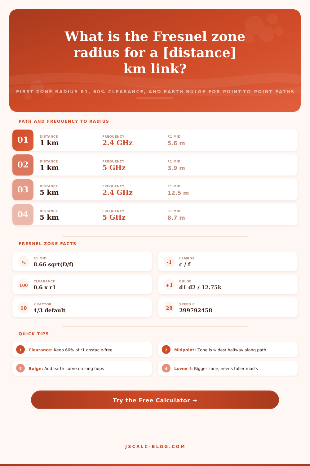
For example, the Fresnel zone is fattest halfway between the antennas. That’s because the distance from each antenna times the other equal the biggest value. The radius (in meters) is approximately equal to 8.66 * the square root of the entire path length/frequency. For a five kilometer link operating at 2.4 GHz, this means that first zone radius is approximately twelve and a half meters.
Anything close to the midpoint of a hop is worse then something near one or both of the antennas. Focus your survey work on the midpoint of the path. Ideally, we want to keep all of the first Fresnel zone open. Instead, there’s a working guideline radio planners follow: If more than sixty percent of the first zone’s radius are kept open, then the diffraction loss will be minimal and negligible. To provide this value, the tool simply multiplies the radius by zero point six. In our case with the twelve and a half meter example, this means maintaining an opening of seven and a half meters. This number can be changed based off your required link budget. But in general, sixty percent is the industry standard.
Within ten kilometers or so, the ground is mostly flat despite small dips. Beyond that, the curvature of the earth raises the surface between antennas. How high that rise gets depend upon the effective earth radius factor. By default this is set at 1.33 (normal atmospheric refraction). At forty kilometers out, the mid-point hump rises more than twenty-three meters. That can dwarf the Fresnel clearance itself. The calculator incorporates that hump into whatever clearance you need. It shows how much vertical space your line of sight require above any obstacle.
The Fresnel zones are fatter. Longer wavelengths equal lower frequencies. You need more clearance for a sub-gigahertz link then for a five gigahertz link across the same distance. Paths increase the width of the zone in proportion to the square root of the distance. At the same time, they introduce earth bulge.
It’s this kind of realism that the built-in presets is designed around. Common deployments from Wi-Fi to microwave links are covered by the presets. These load instantaneously with realistic numbers. That makes it easier to get a bigger tower in your budget.
Once you understand the total clearance it is concrete arithmetic: Add up the height of the bulging earth plus the height of the worst obstacle, plus the minimum clearance at the worst obstacle. Next, make sure each antenna will be tall enough to clear the sight line over the sum.
If your budget only allows shortish masts, don’t panic. There are ways! For example, you might change the frequency to get a narrower zone. Or you could route around the obstacle. Or use more repeater sites to divide the single long hop into multiple shorter hops.
That’s what the tool does; it helps you explore the trade-offs in just a few seconds. It makes an invisible problem real in terms of manageable numbers. You should of seen how easy it is.