Transformer VA Rating Calculator
Size a power transformer from your load. Enter secondary voltage and current for one or more windings to get the volt-ampere (VA) per winding and total VA, add a safety margin and rectifier or inrush allowance, then read the recommended next standard VA size and the primary current drawn on the mains side.
⚡Number of Secondary Windings
📌Real Transformer Sizing Presets
📝Load and Supply Inputs
RMS output voltage of the first winding.
Continuous load current from winding one.
Output voltage of the second winding.
Continuous load current from winding two.
Output voltage of the third winding.
Continuous load current from winding three.
Headroom above load, typically 20 to 25 percent.
Rectifier loads need extra VA for peak charging current.
Real watts = VA x PF. Use 1.0 for resistive loads.
Mains input, e.g. 120 V or 230 V.
Estimates the brief cold switch-on current surge.
Controls rounding on every result card.
🔢Formula Snapshot
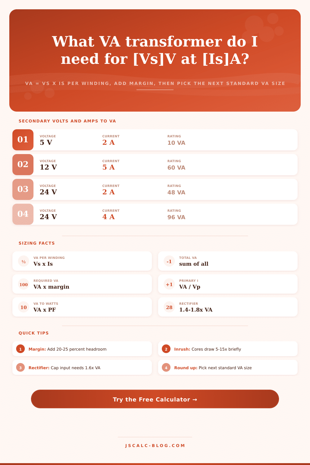
📋Secondary Volts and Amps to VA
| Secondary Voltage | Load Current | VA = Vs × Is | Typical Use |
|---|---|---|---|
| 5 V | 2 A | 10 VA | Logic / USB rail |
| 6.3 V | 3 A | 19.9 VA | Tube heaters |
| 9 V | 1.5 A | 13.5 VA | Effects pedal |
| 12 V | 5 A | 60 VA | LED strip driver |
| 16 V | 1.25 A | 20 VA | Doorbell / chime |
| 18 V | 3 A | 54 VA | Audio amp rail |
| 24 V | 4 A | 96 VA | Industrial control |
| 36 V | 6 A | 216 VA | E-bike charger |
| 48 V | 5 A | 240 VA | CNC / servo PSU |
📏Standard Transformer VA Sizes
| Standard VA | Watts at PF 1 | Ip at 120 V | Ip at 230 V | Common Application |
|---|---|---|---|---|
| 25 VA | 25 W | 0.21 A | 0.11 A | Thermostats, relays |
| 50 VA | 50 W | 0.42 A | 0.22 A | Doorbells, small controls |
| 75 VA | 75 W | 0.63 A | 0.33 A | HVAC control circuits |
| 100 VA | 100 W | 0.83 A | 0.43 A | Landscape / halogen light |
| 150 VA | 150 W | 1.25 A | 0.65 A | Audio power amps |
| 200 VA | 200 W | 1.67 A | 0.87 A | Bench power supplies |
| 300 VA | 300 W | 2.50 A | 1.30 A | CNC / motor drives |
| 500 VA | 500 W | 4.17 A | 2.17 A | Isolation, machine tools |
🔗VA, Watts, and Power Factor
| Quantity | Formula | Meaning | Example |
|---|---|---|---|
| Apparent power | VA = Vs × Is | What the transformer must supply | 24 V × 4 A = 96 VA |
| Real power | W = VA × PF | Actual work delivered | 96 VA × 0.8 = 76.8 W |
| Power factor | PF = W / VA | Ratio of real to apparent | 76.8 / 96 = 0.8 |
| Primary current | Ip = VA / Vp | Mains-side draw | 96 / 120 = 0.8 A |
| Reactive load | VA = W / PF | Size up for motors | 60 W / 0.7 = 85.7 VA |
| Rectifier load | VA = W × 1.6 | Cap-input headroom | 50 W × 1.6 = 80 VA |
🗃Multi-Secondary Sizing Comparison Grid
| Application | Windings | Total VA | +20% Margin | Std Size | Ip at 120 V |
|---|---|---|---|---|---|
| LED strip driver | 12V 5A | 60 VA | 72 VA | 75 VA | 0.63 A |
| Control transformer | 24V 2A | 48 VA | 57.6 VA | 63 VA | 0.53 A |
| Dual-rail audio amp | 18V 3A x2 | 108 VA | 129.6 VA | 150 VA | 1.25 A |
| Tube preamp | 6.3V 3A + 250V 0.1A | 44.9 VA | 53.9 VA | 63 VA | 0.53 A |
| Bench supply | 30V 3A | 90 VA | 108 VA | 150 VA | 1.25 A |
| Halogen lighting | 12V 10A | 120 VA | 144 VA | 150 VA | 1.25 A |
| CNC motor PSU | 48V 5A | 240 VA | 288 VA | 300 VA | 2.50 A |
| Triple-output PSU | 24V 3A + 12V 2A + 5V 2A | 106 VA | 127.2 VA | 150 VA | 1.25 A |
| Isolation unit | 120V 1A | 120 VA | 144 VA | 150 VA | 1.25 A |
⚙Formula Breakdown
💡Transformer Sizing Tips
There you are, standing in the garage with your box of old LED strips and your shiny new power supply which won’t come on. According to label, it’s rated for twelve volts; your load pulls five amps. You pull out a sixty VA transformer; math looks right, so off you go. An hour later, the thing starts to whine loudly and every time you pass by the lights gets dimmer. Bad luck, huh? Nope, just some simple physics.
Your convenience and logic means nothing to transformers. All they care about is the amount of magnetic flux pushing through their iron cores and heat being generated in their copper windings. That’s why getting the size right matter more then most people think. Plugging your numbers into the calculator above do all that math for you (no more guessing and burnt out coils!).
How to Choose the Right Transformer Size
However, there’s one key point about electricity that will help you understand what these numbers represent: volts x amps = VA (or apparent power). Watts is the amount of real work. Most people begins here because this is what’s printed on their appliance boxes. Volt-amps (VA), or apparent power, is what transformers is rated in. In the case of a simple heater, watts and VA is almost equal. Anything involving switching supplies, transformers, or motors means they aren’t. And that’s when projects falls apart.
Maybe you have a motor that draw fifty watts but only performs half the work. It still demands eighty VA from grid, yet transformer only sees the eighty, not the fifty. So if you size based off fifty, then before you even flip the switch, you’re running the unit beyond its thermal capabilities.
It’s simple math, really. The secondary voltage times the current draw per winding equal the VA of each winding added together. An audio amplifier with two windings drawing three amps each give you 108 VA. Voila. This is your starting point.
This is the part that separates a prototype from a product. You don’t purchase a transformer rated this exact amount. Running your core to its limit makes it run hot which, in turn, break down insulation over time. A 20% margin isn’t being overly cautious. It’s peace of mind when the motor kicks in or that song hits that loud volume and you notice some sag in voltage.
That gets complicated with rectifiers. That kind of power supply don’t pull current smoothly at all. It rips current off the line in big spikes right at the top of every AC cycle. Those spikes produces far more heat than a similar resistive load of equal average power. To compensate for that, the tool use a multiplier; typically about one point six for normal designs. The most common error made by builders is to ignore that multiplier. They figure out how many watts of DC they want, and they purchase a transformer marked exactly as much. Then they notice after a week or so that their transformer smells like ozone.
Why? Because it’s supposed to. And there’s a reason why it has the extra VA rating; it can absorbs the peak currents without melting windings.
And then there’s the surge when you turn it on. If the transformer has been off and cold, it could of draw ten or even fifteen times normal current for a few milliseconds while core saturates. For example, a one-hundred-fifty VA may pull twenty amps for a brief moment. Unless you have slow-blow fuses that aren’t going to blow with the brief surge of a couple milliseconds (designed to ignore it), every time you plug it in your fuse will blow. Based off the type of core, the calculator calculate this surge (inrush) so you can select the right protection.
The last bit is what physical piece? Transformers is made in standard increments by manufacturers. Fifty. Seventy-five. One hundred fifty. Three hundred VA. Round up to the next increment. Always having headroom. Short shopping trip. Clean parts list.
It takes less than a minute to calculate, but it saves hours of troubleshooting. No more melted wires, no more whining coil, no more dimming lights. Just a system running cool and lasting for years like it’s supposed to. Those extra volt-amperes you decided to throw in there “just to be safe” are often what separate a silent, reliable build from a frustrating failure.