Transformer Secondary Voltage Calculator
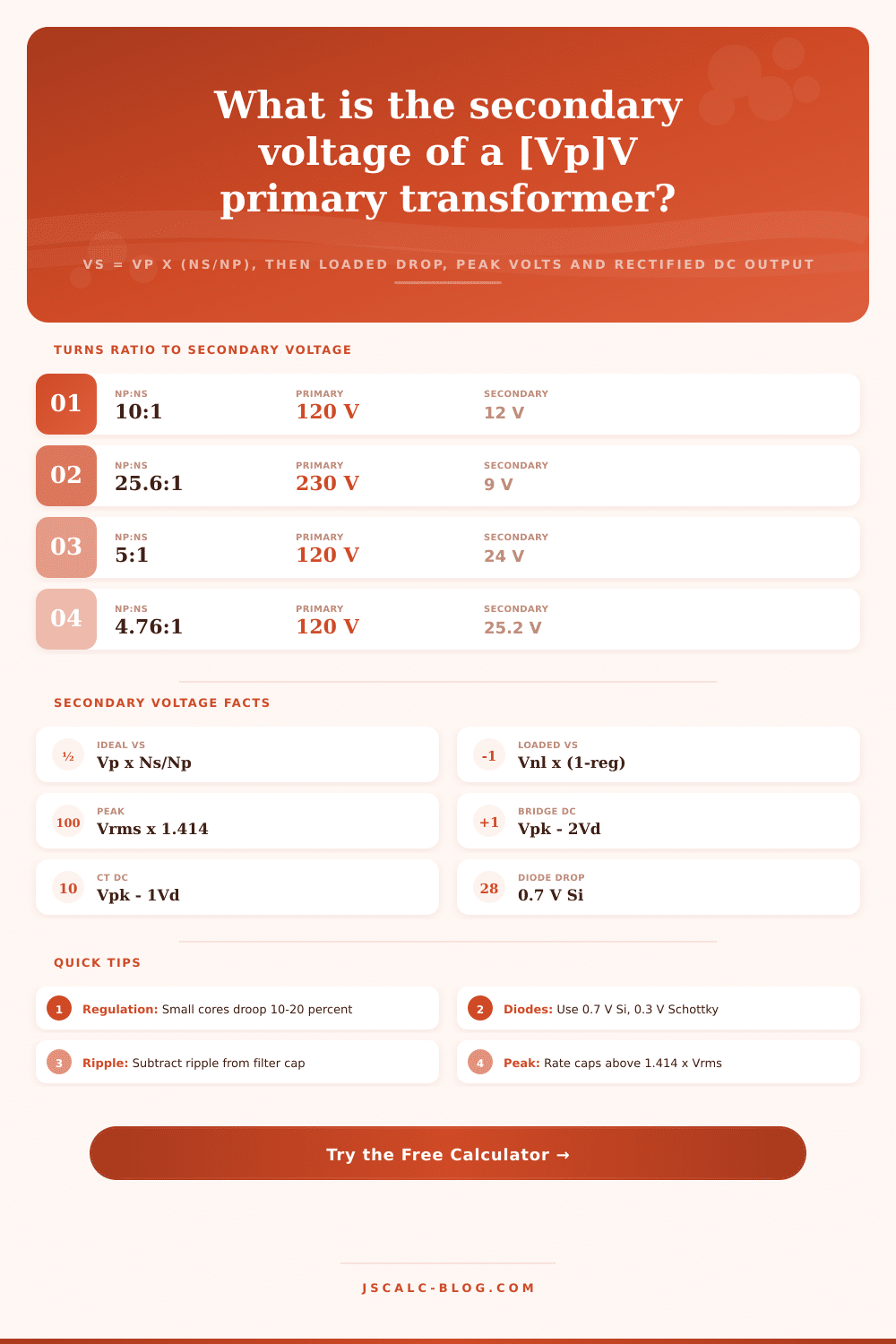
Find the secondary voltage from the turns ratio Vs = Vp x (Ns / Np), then apply winding regulation to get the loaded terminal voltage, the peak voltage Vpk = Vs x 1.414, and the rectified DC output after a full bridge or center-tapped rectifier with its diode drops.
⚡Real Transformer Presets
📝Transformer & Load Inputs
Applied mains or source RMS voltage on the primary.
Number of turns on the primary winding.
Turns on the secondary; sets the turns ratio Ns / Np.
Percent droop from no-load to full-load. Small cores 10-20 percent.
Secondary RMS load current for the winding IR drop.
DC winding resistance. If above 0, drop = I x Rs is used instead of the regulation percent.
Sets how many diode drops subtract from the peak for Vdc.
0.7 V silicon, 0.3 V Schottky, 1.0 V high current.
🔢Formula Snapshot
📋Turns Ratio to Secondary Voltage
| Primary Vp | Ratio Np:Ns | Secondary Vs | Typical Use |
|---|---|---|---|
| 120 V | 10 : 1 | 12 V | Bench and hobby supply |
| 230 V | 25.6 : 1 | 9 V | Wall adapter |
| 120 V | 5 : 1 | 24 V | HVAC control circuit |
| 120 V | 4.76 : 1 | 25.2 V | Center-tapped audio amp |
| 120 V | 7.5 : 1 | 16 V | Doorbell chime |
| 230 V | 36.5 : 1 | 6.3 V | Tube heater, logic rail |
| 120 V | 6.67 : 1 | 18 V | Toroidal preamp |
| 120 V | 1 : 2.5 | 300 V | Tube plate B+ supply |
| 120 V | 1 : 1 | 120 V | Isolation transformer |
📊Peak and Rectified DC From Secondary RMS
| Secondary RMS | Peak (x1.414) | Bridge DC (-1.4V) | Center-Tap DC (-0.7V) | Half-Wave DC (-0.7V) |
|---|---|---|---|---|
| 6.3 V | 8.9 V | 7.5 V | 8.2 V | 8.2 V |
| 9 V | 12.7 V | 11.3 V | 12.0 V | 12.0 V |
| 12 V | 17.0 V | 15.6 V | 16.3 V | 16.3 V |
| 15 V | 21.2 V | 19.8 V | 20.5 V | 20.5 V |
| 18 V | 25.5 V | 24.1 V | 24.8 V | 24.8 V |
| 24 V | 33.9 V | 32.5 V | 33.2 V | 33.2 V |
| 25.2 V | 35.6 V | 34.2 V | 34.9 V | 34.9 V |
| 30 V | 42.4 V | 41.0 V | 41.7 V | 41.7 V |
🔌Diode Drop and Rectifier Reference
| Rectifier | Diodes in Path | Total Drop | DC Formula |
|---|---|---|---|
| Full bridge | 2 conducting | 2 x Vd | Vpk - 2Vd |
| Center-tap full wave | 1 per half | 1 x Vd | Vpk - Vd |
| Half wave | 1 diode | 1 x Vd | Vpk - Vd |
| Silicon (1N400x) | - | 0.7 V each | Standard rectifier |
| Schottky | - | 0.3 V each | Low loss, low V rails |
| High current (6A) | - | 1.0 V each | Heavy load droop |
🗃Loaded Secondary Voltage Comparison Grid
| Application | No-Load Vs | Regulation | Full-Load Vs | Peak V | Bridge DC |
|---|---|---|---|---|---|
| 120V:12V Bench | 12.0 V | 12% | 10.6 V | 14.9 V | 13.5 V |
| 230V:9V Adapter | 9.0 V | 18% | 7.4 V | 10.4 V | 9.0 V |
| 120V:24V HVAC | 24.0 V | 10% | 21.6 V | 30.5 V | 29.1 V |
| 25.2V CT Audio | 25.2 V | 8% | 23.2 V | 32.8 V | 31.4 V |
| 120V:16V Doorbell | 16.0 V | 20% | 12.8 V | 18.1 V | 16.7 V |
| 120V:18V Toroid | 18.0 V | 6% | 16.9 V | 23.9 V | 22.5 V |
| 230V:6.3V Rail | 6.3 V | 15% | 5.4 V | 7.6 V | 6.2 V |
| 120V:120V Isolation | 120 V | 4% | 115 V | 163 V | 161 V |
⚙Formula Breakdown
💡Design and Safety Tips
What will the secondary actualy deliver when it has a rectifier and a load connected? That’s the practical question that’s answered by the transformer secondary voltage calculator on this page. A datasheet number rarely tells the whole story. Why not? This is because the loaded winding voltage do not match the theoretical turns ratio, and the rectified DC voltage is different too.
This tool walks the entire chain: from turns ratio to no-load RMS, to loaded RMS, to peak, and then to rectified DC output. Why not? Because the voltage at the winding with load isn’t the same as the theoretical turns ratio figure; and the DC after rectification isn’t the same either. This tool walks the entire chain: from turns ratio to no-load RMS, to loaded RMS, to peak, and then to rectified DC output.
How to Calculate Real Transformer Voltage
A perfect transformer increases (or decreases) voltage in direct proportion to the turns. The formula is Vs = Vp x Ns/Np, where Ns and Np are the turns on each side and Vp is the RMS voltage going into the primary. Wind less turns on your secondary then the primary and you’ve stepped the voltage down. More and you’ve stepped it up.
For example, if your primary has 1000 turns at 120 V RMS and your secondary is only 100 turns, that’s 12 V RMS out. There is no load. The calculator also tells you what the ratio is, so you don’t just get the answer but see how it works too.
When current does flow, the terminal voltage immediately starts to sag because real windings has leakage inductance and resistance. To describe this, engineers use voltage regulation, shown as percentage drop between no load and full load. For example, a 12 V rated winding with 15 percent regulation will only produce around 10.2 V under full load. That’s where folks go astray.
When you enter a regulation percentage here, this calculator uses the equation for loaded secondary voltage. Switch to the resistance method if you already know the secondary DC resistance. Simply enter its ohms and load current and it subtracts the drop due to Ohm’s law. The smaller the transformer, the worse the regulation, typically 10 to 20 percent; the larger the toroid, the closer to a few percent.
And then there’s the other side: once you have the loaded RMS voltage, what does the peak matter? Well, that’s because the filter capacitor is charging to the top (the crest) of the waveform, not to the average. On a sine wave, the peak is Vpk = Vrms × √2. That’s 1.414 times the RMS value. So a 12 V RMS secondary gets charged up to about 17 V, and a 24 V RMS secondary get charged up to something like 34 V.
That’s why the voltage rating on capacitors and semiconductors has to be based on the peak, not the nameplate RMS. With the peak secondary card it’s right there in your face, never something anyone would think was an afterthought.
The last step removes the voltage lost to the diodes as they rectify. Two diodes pass in series on each half cycle for a full bridge. So it’s Vpk minus 2 times Vd (DC) out. For a center-tapped full wave rectifier, only one diode passes on each half cycle. So there’s just a single drop.
With your typical silicon diodes at 0.7 V, a peak of 17 V results in roughly 15.6 V DC from a bridge or 16.3 V DC from a center tap. Drop down to Schottky diodes at 0.3 V and you get a bit back. And that’s where it really counts when trying to preserve some voltage on a low-voltage logic rail.
Four result cards hold all of the math. One card holds the secondary voltage with no load, which is your ideal turns ratio voltage. The second is the full load secondary, which includes the voltage drop from regulation or resistance. The third is the peak secondary which is what the capacitor sees. The last one is the rectified DC output.
This comes after smoothing through a rectifier, which include the diode drops, and then a bit more smoothing from the filter ripple. Below that, the formulas are broken out into panels. This lets you see where each number came from line by line if you want to do your own hand calculations. It also helps you catch any places where the design isn’t leaving much room for error.
Depending on your rectifier selector, that means that you will have one or more of those diode drops subtracted off the top. A center tapped full wave uses only half the winding at once but still incurs a single drop. A full bridge needs no center tap and use the whole secondary, but costs two diode drops. It is a trade-off between efficiency and the number of components, and it has been historically preferred for high current, low voltage rails. Half wave rectification is simplest, requiring the biggest filter cap and wasting half the cycle.
Take an example: You need a bench output of 12 V DC regulated. Transformer from 120 V AC to 12 V RMS yields 12 V RMS unloaded. With 12 percent regulation, you have 10.6 V RMS on the secondary under a load. Peak is 15.0 V. Passing this through a full bridge with silicon diodes drops the DC to 13.6 V (before ripple). Now there’s barely any headroom over 12 V for a linear regulator. Safer to go with a 15 V secondary.
Transformers have a primary voltage. Rectifiers has a diode drop. Windings have a regulation value. Loads have a voltage when loaded. Add all those together and it’s easy to guess at the wrong secondary voltage, resulting in a regulator starved for head room, or supplies that sag under a load. This tool chains the turns ratio, the loaded drop, the peak, and the rectified DC into a single view so you can size your rectifier and transformer with confidence in seconds.
Load a preset, adjust the primary voltage, turns, regulation, load current, rectifier type, and diode drop; read the breakdown and cards. It delivers numbers grounded in real transformer physics whether you are building an audio supply, designing an HVAC control circuit, or repairing a doorbell transformer. The datasheet tells part of the story, but the loaded peak brings it home.