Transformer Turns Ratio Calculator
Work out the turns ratio n = Np/Ns = Vp/Vs from any two known values, read the inverse current ratio Is/Ip, and reflect a load through the winding using the n squared impedance rule. The tool also flags whether the design steps voltage up or down.
⚡Choose What You Know
🔌Real Transformer Presets
📝Transformer Inputs
RMS voltage applied to the primary winding.
Open-circuit RMS voltage at the secondary.
Number of wire turns on the primary coil.
Number of wire turns on the secondary coil.
Impedance connected on the secondary side.
Impedance the primary should present to the source.
Real power drawn by the load, for current estimates.
Rounding applied to every result card.
🔢Ratio Snapshot
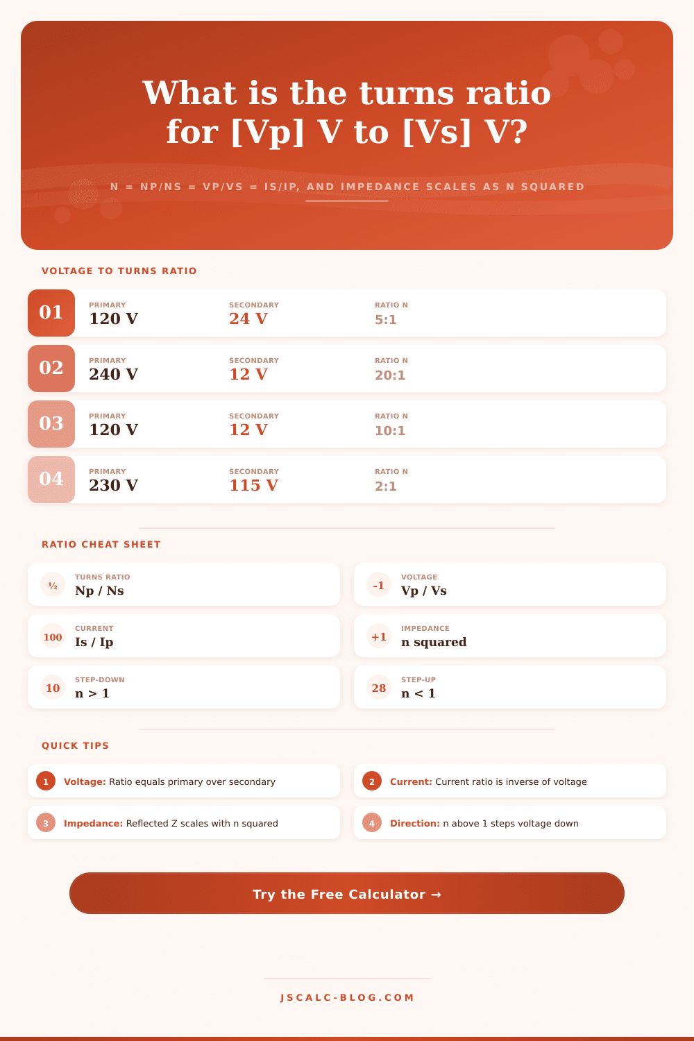
📋Voltage Ratios of Common Transformers
| Primary Vp | Secondary Vs | Turns Ratio n | Direction |
|---|---|---|---|
| 120 V | 24 V | 5 : 1 | Step-down |
| 240 V | 12 V | 20 : 1 | Step-down |
| 120 V | 12 V | 10 : 1 | Step-down |
| 230 V | 115 V | 2 : 1 | Step-down |
| 277 V | 120 V | 2.31 : 1 | Step-down |
| 480 V | 120 V | 4 : 1 | Step-down |
| 120 V | 240 V | 1 : 2 | Step-up |
| 12 V | 120 V | 1 : 10 | Step-up |
🔉Impedance Reflection by Turns Ratio
| Turns Ratio n | Impedance Ratio n squared | Load Zs | Reflected Zp | Use Case |
|---|---|---|---|---|
| 1 : 1 | 1 | 8 ohm | 8 ohm | Isolation |
| 2 : 1 | 4 | 8 ohm | 32 ohm | Line matching |
| 5 : 1 | 25 | 8 ohm | 200 ohm | Signal pad |
| 10 : 1 | 100 | 8 ohm | 800 ohm | 70V line tap |
| 22.4 : 1 | 500 | 8 ohm | 4000 ohm | Audio output |
| 25 : 1 | 625 | 8 ohm | 5000 ohm | Tube plate load |
| 1 : 4 | 0.0625 | 4000 ohm | 250 ohm | Antenna balun |
🗄Turns Ratio Design Comparison Grid
| Application | Primary Vp | Secondary Vs | Ratio n | Current Ratio Is/Ip | Zp for 8 ohm Load | Type |
|---|---|---|---|---|---|---|
| Doorbell | 120 V | 24 V | 5 : 1 | 5 | 200 ohm | Step-down |
| Halogen lamp | 240 V | 12 V | 20 : 1 | 20 | 3200 ohm | Step-down |
| Wall wart | 120 V | 12 V | 10 : 1 | 10 | 800 ohm | Step-down |
| USB charger | 120 V | 5 V | 24 : 1 | 24 | 4608 ohm | Step-down |
| Isolation | 230 V | 230 V | 1 : 1 | 1 | 8 ohm | Isolation |
| Inverter boost | 12 V | 120 V | 1 : 10 | 0.1 | 0.08 ohm | Step-up |
| Distribution buck | 480 V | 120 V | 4 : 1 | 4 | 128 ohm | Step-down |
| Microwave HV | 120 V | 2100 V | 1 : 17.5 | 0.057 | 0.026 ohm | Step-up |
| Audio output | - | - | 22.4 : 1 | 22.4 | 4000 ohm | Matching |
| Tube plate | - | - | 25 : 1 | 25 | 5000 ohm | Matching |
🔗Turns Ratio to Ratio Notation
| Value of n | Ratio Notation | Voltage Effect | Current Effect |
|---|---|---|---|
| 10 | 10 : 1 | Vs is 1/10 of Vp | Is is 10x Ip |
| 2 | 2 : 1 | Vs is half of Vp | Is is 2x Ip |
| 1 | 1 : 1 | Vs equals Vp | Is equals Ip |
| 0.5 | 1 : 2 | Vs is 2x Vp | Is is half of Ip |
| 0.1 | 1 : 10 | Vs is 10x Vp | Is is 1/10 of Ip |
| 0.057 | 1 : 17.5 | Vs is 17.5x Vp | Is is 1/17.5 Ip |
⚙Formula Breakdown
💡Transformer Design Tips
Ever melt a transformer after it had been working perfectly for years? Chances are you got size right on the primary side but forgot about the current on the secondary side. Most folks miss that one.
Once you enter either your winding count or your voltage into the turns ratio calculator, it do all the math for you. This eliminates guesswork about whether a device steps down or up voltages. What it can do to is tell you exactly how much impedance looks different based off the other side of the coil…critical when you’re matching a power supply to a load, or an amplifier to a speaker.
Why You Need to Know Your Turns Ratio
Here’s how a transformer works: It’s simply a pair of wires wound around a common magnetic core. By running alternating current through the primary winding, it generates a magnetic field that change with time and thereby induces a voltage in the second winding. The flux passes through both windings, so each coil experience the same voltage per turn. For instance, if the primary has five times as many turns than the secondary, it will have five times the voltage. This relationship (n) is called turns ratio, typically expressed as n = Np/Ns. Since n = 1 represents no change, anything bigger than one mean you’re stepping down, while anything smaller than one is step-up.
And that’s where the tool comes into play, it will let you do this from three different angles. If your nameplate data shows the primary and secondary voltages, then input those. If you’re looking at a coil specification or rewinding a core, then input actual number of turns. Or, if you want to know what ratio gives maximum power transfer between two impedance (the one from which the other takes power), input the source and load impedances. This is by far the most common day-to-day application, since many times the entire purpose of including a transformer in a signal path are impedance matching, not merely a change in voltage levels.
OK, here’s where it gets interesting. Because transformers is ideal (meaning they conserve power), their input must have the same product of volts times amps as their output. To maintain that balance, the current has to shares in the opposite direction of the voltage. So when you step down the voltage by a factor of ten, the current will jump up by a factor of ten to preserve that conservation law. This is the opposite relationship reported plainly by the calculator; it also explain why thick wire is required for the low-voltage side of any transformer. A 120 volt to 12 volt transformer that puts out 60 watts pulls only half an amp on the primary and five amps on the secondary. Overheating windings and burnt-out connectors is commonly caused by ignoring that spike of current.
To make matters even more interesting, impedance also doesn’t scale directly with turns ratio, but instead scales as square of the ratio. Looking from the primary side of a transformer, an impedance on its secondary will be scaled up by the square of the ratio. This means a modest 5 to 1 turns ratio will multiply impedance by 25 and turn an 8 ohm speaker into a 200 ohm load for the amplifier driving it. Because of that fast-growing effect, small adjustments in winding ratio rapidly change the reflected impedance. On page you’ll find a reference table laying all this out for common audio applications. In these cases, a tube amp often need a certain ratio to present the correct plate load to the tubes.
After calculation, it generate four result cards for most designers to look at to make their call. One card has the raw turns ratio and shows if it’s a step-up or step-down config. Another shows the current ratio so you know how much conductor to size. A third applies the square law to show what the load will look like from the source side. These numbers helps you see the full picture before you buy wire or cut any cores. Knowing how voltage trades off vs. Current vs. Impedance in your design help you keep your design efficient and safe.
It could of being something as simple as checking out an old doorbell transformer or designing a custom audio matching network, but you must understand the turns ratio as a number that dictates how energy flows through your entire system.