Impedance Magnitude Calculator
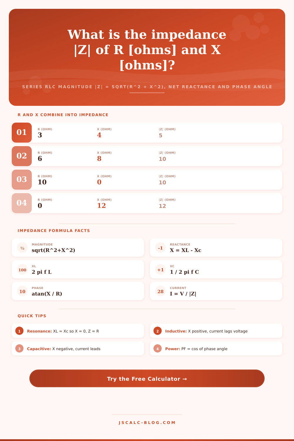
Combine resistance R with inductive reactance XL and capacitive reactance Xc into the total series impedance. This tool returns the net reactance X = XL - Xc, the impedance magnitude |Z| = sqrt(R^2 + X^2), the phase angle in degrees, the power factor, and the current I = V / |Z| when you supply an applied voltage.
⚡Choose an Input Mode
🎯Real Circuit Presets
🔌Circuit Inputs
Total series resistance; may be 0 for an ideal reactance.
Reactance of the inductor at the operating frequency.
Reactance of the capacitor at the operating frequency.
Used with frequency to compute XL = 2 pi f L.
Applies to the inductance field above.
Used with frequency to compute Xc = 1 / (2 pi f C).
Applies to the capacitance field above.
Operating frequency for the reactance calculations.
Applies to the frequency field above.
RMS volts across the branch; leave 0 to skip current.
Controls rounding on every result card.
🔢Formula Snapshot
📏How R and X Combine into |Z|
| Resistance R | Net Reactance X | |Z| = sqrt(R^2+X^2) | Phase atan(X/R) |
|---|---|---|---|
| 3 ohm | 4 ohm | 5 ohm | 53.13 deg |
| 6 ohm | 8 ohm | 10 ohm | 53.13 deg |
| 10 ohm | 0 ohm | 10 ohm | 0 deg |
| 0 ohm | 12 ohm | 12 ohm | 90 deg |
| 5 ohm | 5 ohm | 7.07 ohm | 45 deg |
| 8 ohm | 6 ohm | 10 ohm | 36.87 deg |
| 12 ohm | 5 ohm | 13 ohm | 22.62 deg |
| 7 ohm | -24 ohm | 25 ohm | -73.74 deg |
📈Phase Angle and Power Factor
| Phase Angle theta | Power Factor cos theta | Circuit Behavior | Current vs Voltage |
|---|---|---|---|
| 0 deg | 1.000 | Purely resistive | In phase |
| 15 deg | 0.966 | Mostly resistive | Current lags |
| 30 deg | 0.866 | Weakly inductive | Current lags |
| 45 deg | 0.707 | R equals X | Current lags |
| 60 deg | 0.500 | Strongly inductive | Current lags |
| 90 deg | 0.000 | Pure inductor | Lags 90 deg |
| -45 deg | 0.707 | R equals Xc | Current leads |
| -90 deg | 0.000 | Pure capacitor | Leads 90 deg |
🔌Reactance at Common Frequencies
| Component | Value | Frequency | Reactance | Type |
|---|---|---|---|---|
| Inductor | 10 mH | 60 Hz | 3.77 ohm | XL rises with f |
| Inductor | 1 mH | 1 kHz | 6.28 ohm | XL rises with f |
| Inductor | 100 uH | 10 kHz | 6.28 ohm | XL rises with f |
| Capacitor | 10 uF | 60 Hz | 265.3 ohm | Xc falls with f |
| Capacitor | 1 uF | 1 kHz | 159.2 ohm | Xc falls with f |
| Capacitor | 100 nF | 10 kHz | 159.2 ohm | Xc falls with f |
| Capacitor | 470 uF | 120 Hz | 2.82 ohm | Ripple filter |
🗃Series RLC Impedance Comparison Grid
| R (ohm) | XL (ohm) | Xc (ohm) | X = XL - Xc | |Z| (ohm) | Phase (deg) |
|---|---|---|---|---|---|
| 100 | 0 | 0 | 0 | 100.00 | 0.00 |
| 10 | 20 | 5 | 15 | 18.03 | 56.31 |
| 8 | 6 | 6 | 0 | 8.00 | 0.00 |
| 5 | 2 | 10 | -8 | 9.43 | -57.99 |
| 3 | 10 | 6 | 4 | 5.00 | 53.13 |
| 4 | 3 | 0 | 3 | 5.00 | 36.87 |
| 50 | 60 | 20 | 40 | 64.03 | 38.66 |
| 20 | 0 | 15 | -15 | 25.00 | -36.87 |
| 12 | 16 | 7 | 9 | 15.00 | 36.87 |
| 6 | 8 | 8 | 0 | 6.00 | 0.00 |
⚙Formula Breakdown
💡Impedance Design Tips
When looking at an AC circuit schematic, you might feel like resistance is lying to you, but impedance is actualy the quantity that captures everything and helps you predict current and power. Sure enough: In DC circuits, resistance do act consistently; it resists current and turns energy into heat. Alternating current adds elements like capacitors and inductors. Devices that can absorbs energy from or give up energy to the driving voltage out of sync with it. That’s when we combine resistance and reactance into a single magnitude called impedance that includes everything.
The calculator on this page do the vector math needed to turn those three individual values into one number used to predict things like power factor and current. No matter what the frequency, the current is resisted by opposition that converts electricity to heat. On the other hand, an inductor resist a change in current (hence the term inductive), so it increases with frequency. A capacitor resists a change in voltage (hence the term capacitive), so it decreases with frequency. Like resistance, each is expressed in ohms; however, neither dissipates energy but instead stores and releases it.
How to Calculate Impedance in AC Circuits
Since these can’t be added arithmetically as if you were adding R, XL and Xc, you have to combine them, like the sides of a right triangle. That’s why the equation is geometrical pretending to be electronics. That’s because there are two steps to the calculation. Step one: determine net reactance. Capacitive reactance cancels out (partially or completely) inductive reactance. You just subtract the capacitive from the inductive. A circuit containing both an inductor and some capacitance will have a net reactance less than amount of the inductor, but greater than zero if the capacitance isn’t too large.
Step two is to add the net reactance and the resistance using the Pythagorean relationship. The magnitude of impedance equals the square root of R squared plus X squared. That means that a circuit with three ohms of resistance and four ohms of net reactance would have a magnitude of impedance equal to five ohms. You’ll see that familiar three-four-five triangle pop up again and again in AC circuitry precisely because of this.
You do not need to memorize component values to get your answer. Want to just plug in numbers? The calculator allows you to type in reactances if they’re known either from a previous calculation or based off the datasheet. Or perhaps you don’t even have that; maybe you just know what components are present and what frequency they’ll be running at. Toggle the mode back and forth and let the calculator calculate reactances based on standard capacitance and inductance formulas. There are unit selectors for both capacitors (picofarads, nanofarads, etc.) and inductors (millihenries, microhenries, henries). From there it’s a few more clicks to a complete impedance answer.
What’s the phase angle? The phase angle tells you how closely the voltage and current line up in terms of timing. If the angle is zero degrees then the net reactance of the circuit is zero and voltage and current go hand-in-hand perfectly in sync (together). If it’s a positive angle, then the circuit has a net inductance and the current lags the voltage (as motors do and transformers do, classic). If it’s a negative angle, then the circuit has a net capacitance and the current leads the voltage. So that’s where that angle is important; just by seeing the sign of the angle you can quickly diagnose what kind of load you have.
That’s the piece that folks who only look at magnitude tend to miss. That’s the phase angle, and its cosine is called “power factor,” or what fraction of the apparent power is doing any useful work at all. A pure resistance will have power factor of 1; a highly reactive load could be close to zero. Why do utilities care? Because if you’re a load with a lousy power factor, they have to send more current down the wire for the same amount of useful power, wasting money and heating up the wires.
The calculator also outputs the branch current if you plug in an applied voltage. Otherwise, just leave it as zero. In that case, it ignores the voltage and focuses only on the branch impedance characteristics.
There’s one exception to all these rules that we should mention. If the inductive reactance happens to equal the capacitive reactance, then the total reactance becomes zero. That means the size of the impedance reduces to only the resistance (R) and the phase angle also goes to zero. That’s what we call series resonance, the condition that creates the lowest impedance. It’s used by radio tuners and filters which are designed to pick up signals at certain frequencies but not at other ones. Here are some resonant circuits that show how the impedance collapses down to its minimall value when the two reactances cancel each other out.
The presets derived from actual circuits bridge the gap between theory and practice: for instance, you can use pure resistive loads, an inductive motor branch, or a capacitive correction branch and watch the numbers change immediately. If you’re an engineering student studying up on AC theory, a hobbyist trying to size a speaker crossover, or an engineer double-checking the load profile of some branch, this tool will turn what would of been a step-by-step computation into one solid answer. It is no replacement for understanding, but the arithmetic friction that takes the fun out of a design’s tradeoffs is gone. Even when your circuit becomes complicated, the triangle stays a right-angle.