Inductive Reactance Calculator
Compute inductive reactance with XL = 2 pi f L in ohms, then solve backwards for the inductance or the frequency, work out the AC current from I = V / XL, and read the 90 degree phase shift where the voltage across a coil leads its current. Reactance rises with frequency, so a coil passes DC and blocks high frequencies.
⚡Real Inductor Presets
📌Inductor and Signal Inputs
Pick the unknown; the matching field below is used as the target.
AC signal frequency. At 0 Hz (DC) reactance is zero.
Coil inductance. Larger coils give more reactance.
Used when you solve for inductance or frequency.
RMS volts across the coil, used to find current I = V / XL.
Controls rounding on every result card.
🔢Formula Snapshot
📋Reactance at Common Frequencies
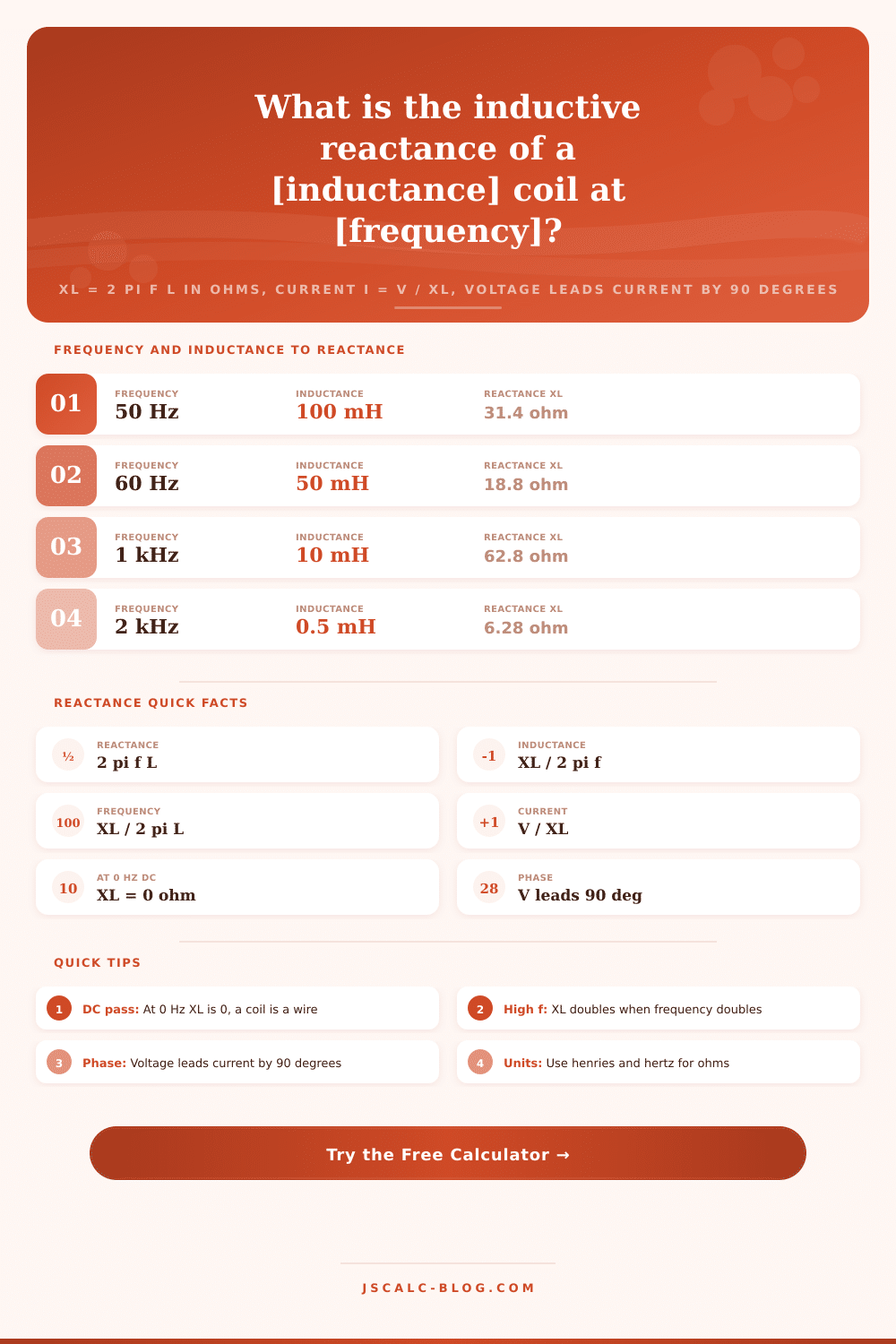
| Frequency f | Inductance L | XL = 2 pi f L | Behaviour |
|---|---|---|---|
| 0 Hz (DC) | 100 mH | 0 ohm | Acts as plain wire |
| 50 Hz | 100 mH | 31.4 ohm | Mains frequency |
| 60 Hz | 50 mH | 18.8 ohm | US line reactor |
| 1 kHz | 10 mH | 62.8 ohm | Audio band |
| 10 kHz | 1 mH | 62.8 ohm | Ultrasonic |
| 100 kHz | 1 mH | 628 ohm | Switching supply |
| 1 MHz | 10 uH | 62.8 ohm | AM radio band |
| 10 MHz | 1 uH | 62.8 ohm | Shortwave RF |
📊How XL Rises With Frequency
| Inductance | XL at 50 Hz | XL at 1 kHz | XL at 100 kHz | XL at 1 MHz |
|---|---|---|---|---|
| 0.1 mH | 0.031 ohm | 0.628 ohm | 62.8 ohm | 628 ohm |
| 1 mH | 0.314 ohm | 6.28 ohm | 628 ohm | 6.28 kohm |
| 10 mH | 3.14 ohm | 62.8 ohm | 6.28 kohm | 62.8 kohm |
| 100 mH | 31.4 ohm | 628 ohm | 62.8 kohm | 628 kohm |
| 1 H | 314 ohm | 6.28 kohm | 628 kohm | 6.28 Mohm |
🗃Frequency, Inductance, Reactance and Current Grid
| Frequency | Inductance | Reactance XL | Current at 10 V | Phase | Typical Use |
|---|---|---|---|---|---|
| 50 Hz | 100 mH | 31.4 ohm | 0.318 A | V leads 90 deg | Mains choke |
| 60 Hz | 50 mH | 18.8 ohm | 0.531 A | V leads 90 deg | Line reactor |
| 1 kHz | 10 mH | 62.8 ohm | 0.159 A | V leads 90 deg | Audio inductor |
| 2 kHz | 0.5 mH | 6.28 ohm | 1.592 A | V leads 90 deg | Speaker crossover |
| 10 kHz | 1 mH | 62.8 ohm | 0.159 A | V leads 90 deg | Ultrasonic coil |
| 100 kHz | 1 mH | 628 ohm | 0.016 A | V leads 90 deg | EMI filter |
| 1 MHz | 10 uH | 62.8 ohm | 0.159 A | V leads 90 deg | AM tuning coil |
| 10 MHz | 1 uH | 62.8 ohm | 0.159 A | V leads 90 deg | RF choke |
📏Frequency and Inductance Unit Conversions
| Unit | Equals | In Base Unit | Note |
|---|---|---|---|
| 1 kHz | 1000 Hz | 1000 Hz | Kilohertz |
| 1 MHz | 1000 kHz | 1000000 Hz | Megahertz |
| 1 mH | 0.001 H | 0.001 H | Millihenry |
| 1 uH | 0.001 mH | 0.000001 H | Microhenry |
| 1 kohm | 1000 ohm | 1000 ohm | Kilohm reactance |
| 2 pi | 6.2832 | 6.2832 rad | One cycle in radians |
⚙Formula Breakdown
💡Inductor Design Tips
Until you pass an alternating current through a coil of wire, that’s just copper wire. When you pass current through it, the coil oppose changes by storing energy as a magnetic field. That opposition isn’t “resistance” as such; it’s what we call inductive reactance. Reactance vary with frequency while resistance does not.
The calculator up top will do math for you if you want to know how much actual opposition results from a given inductance at any frequency. For instance, why did that choke get hot? Or why didn’t this filter work? That’s the key equation: XL = 2 pi f L. It conceals fact that an inductor lets DC flow freely and resists radio frequencies. Reactance is zero ohms at zero hertz; DC passes right through the coil as if it were a piece of straight wire.
How Inductors Work
Chokes smooth ripple on power supplies by permitting steady DC to flow while blocking out high-frequency noise. The reactance calculator has no problem with the limit. Enter a frequency of zero, and it will spit back zero reactance. That means that the coil doesn’t oppose constant flow… Only change.
Finally, inductors is measured in henrys, and this is where people screw up on unit conversion all the time. A henry is big, very big for electronic applications; typically, you’re dealing with microhenries or even millihenries. No need to worry about that… It’s handled internally in the tool. Just choose MHz or kHz and away you go. Because the numbers get pretty small, a fractional decimal change makes the difference between a functioning filter and a short circuit. To help you, there are preset buttons. For example, you can load real-world examples like mains chokes to give you a starting point to tweak.
Here you see it resist current at that same frequency. And you can see how far off its current is relative to voltage. In other words, the calculator reports two numbers for the coil: phase, which shows how much the current is out of sync with the voltage, and magnitude, which shows how much current is being resisted. This tells us that current is lagging behind voltage by 90 degrees. Why does that matter? Because it affects signal integrity and power factor. What it also means, though, is the way component stores energy: via that delay.
To illustrate this, think of a loudspeaker crossover that uses a series inductor to route bass to the woofer while sending treble away. Why? An inductor’s reactance increases with frequency. It has little impact on bass, but it increasingly prevents high notes from reaching the cone. The chart of reference shows that even small values of inductance cause significant opposition at higher frequencies. It seems exponential; frequency increase rapidly on the chart.
Alternatively, if you already have an idea of what reactance you need and want to keep current limited, just enter that into the second input. It will solve for inductance. That’s useful in things like LED dimmer circuits where a coil take the place of a resistive load to prevent waste of energy as heat. By re-arranging the equation, the calculator provides L as the answer.
However, real-world coils contain their own series resistance due to wire inside them. The calculator returns the perfect reactive component, but in reality there is some loss that causes heating because the coil’s physical parts adds resistance. In something sensitive this could impact efficiency. But that loss are slight. It explains the interplay of all these things: frequency, time, and magnetic fields.
You start to realize that the coil isn’t simply a part, it’s a sort of filter based off frequency. When you’re tuning an antenna or trying to troubleshoot an EMI filter, you’ll think differently about the schematic when you understand how its reactance scales with changes in signal speed. The math doesn’t change. Intuition does.
Put some numbers in and let it show you what happens. It is physics, not magic.