Capacitive Reactance Calculator
Find capacitive reactance with Xc = 1 / (2 pi f C) in ohms, then solve backwards for the capacitance or frequency you need. Enter an optional AC voltage to get the current I = V / Xc. Reactance falls as frequency or capacitance rises, and the current through an ideal capacitor leads the voltage by 90 degrees.
⚡Real Circuit Presets
🔢Reactance Inputs
Pick the unknown; the matching field below is disabled.
AC signal frequency. At 0 Hz (DC) reactance is infinite.
1 kHz = 1000 Hz, 1 MHz = 1,000,000 Hz.
Value marked on the capacitor. Larger C lowers Xc.
1 uF = 1000 nF = 1,000,000 pF.
Used when you solve for capacitance or frequency.
RMS volts. Leave 0 to skip the current result.
Controls rounding on every result card.
📏Formula Snapshot
📈Reactance vs Frequency for 1 uF
| Frequency | Angular 2 pi f | Reactance Xc | Behaviour |
|---|---|---|---|
| 0 Hz (DC) | 0 rad/s | Infinite | Blocks DC |
| 20 Hz | 126 rad/s | 7958 ohm | Very high |
| 50 Hz | 314 rad/s | 3183 ohm | Mains low end |
| 60 Hz | 377 rad/s | 2653 ohm | Mains US |
| 1 kHz | 6283 rad/s | 159.2 ohm | Audio mid |
| 10 kHz | 62832 rad/s | 15.92 ohm | Audio high |
| 100 kHz | 628 krad/s | 1.592 ohm | Near short |
| 1 MHz | 6.28 Mrad/s | 0.159 ohm | RF, tiny Xc |
📊Reactance at 1 kHz Across Capacitor Values
| Capacitance | Typical Use | Xc at 1 kHz | Xc at 100 kHz |
|---|---|---|---|
| 10 pF | RF trimmer | 15.9 Mohm | 159 kohm |
| 100 pF | RF coupling | 1.592 Mohm | 15.92 kohm |
| 1 nF | Filter cap | 159.2 kohm | 1592 ohm |
| 10 nF | Snubber | 15.92 kohm | 159.2 ohm |
| 100 nF | Decoupling | 1592 ohm | 15.92 ohm |
| 1 uF | Coupling | 159.2 ohm | 1.592 ohm |
| 10 uF | Bulk bypass | 15.92 ohm | 0.159 ohm |
| 470 uF | SMPS output | 0.339 ohm | 0.0034 ohm |
🔌Frequency and Capacitance Comparison Grid
| Frequency | Capacitance | Reactance Xc | I at 10 V | Phase | Note |
|---|---|---|---|---|---|
| 50 Hz | 1 uF | 3183 ohm | 3.14 mA | I leads 90 | Mains filter |
| 60 Hz | 10 uF | 265.3 ohm | 37.7 mA | I leads 90 | PFC cap |
| 440 Hz | 1 uF | 361.7 ohm | 27.6 mA | I leads 90 | Audio tone |
| 1 kHz | 100 nF | 1592 ohm | 6.28 mA | I leads 90 | Coupling |
| 10 kHz | 100 nF | 159.2 ohm | 62.8 mA | I leads 90 | Audio high |
| 100 kHz | 10 nF | 159.2 ohm | 62.8 mA | I leads 90 | Snubber |
| 100 kHz | 470 uF | 0.0034 ohm | 2954 A | I leads 90 | SMPS bulk |
| 1 MHz | 100 pF | 1592 ohm | 6.28 mA | I leads 90 | RF bypass |
| 1 MHz | 100 nF | 1.592 ohm | 6.28 A | I leads 90 | Decouple |
| 10 MHz | 100 pF | 159.2 ohm | 62.8 mA | I leads 90 | HF bypass |
🔄Unit Multipliers Used
| Unit | Symbol | In Base Unit | Applies To |
|---|---|---|---|
| Hertz | Hz | 1 Hz | Frequency |
| Kilohertz | kHz | 1000 Hz | Frequency |
| Megahertz | MHz | 1000000 Hz | Frequency |
| Picofarad | pF | 1e-12 F | Capacitance |
| Nanofarad | nF | 1e-9 F | Capacitance |
| Microfarad | uF | 1e-6 F | Capacitance |
⚙Formula Breakdown
💡Practical Capacitor Tips
This is a capacitive reactance calculator. This is another useful calculator based off a basic relationship among AC electronics. Xc is capacitive reactance, or how much a capacitor opposes an alternating current flow. That’s expressed by the formula Xc = 1 / (2 pi f C). The result of that calculation are in ohms.
Unlike a simple resistor, however, capacitive reactance vary with frequency. The higher the frequency, the lower the capacitor’s reactance. This calculator computes all aspects of the formula. If you know any two variables, it will solve for remaining one. It changes the formula so you can calculate either the required capacitance or frequency.
How to Use This Calculator
And if you provide a voltage across the part, it calculates the AC current flowing through component using the formula: I = V / Xc. Both reactance and resistance is expressed in ohms. Both act as a limiting force on current. However, resistance is due to loss of energy, while reactance is due to storage of energy. For example: In a capacitor, there’s charge stored in an electric field that gets released with each cycle. Because of this, the capacitor resists change in voltage; it doesn’t waste power.
One equation says this all: Xc = 1 / (2 pi f C). That’s where we get two things in one shot. One, the bigger the capacitance, C, the greater amount of charge for any given amount of voltage. Which lowers the reactance. Two, the faster the frequency, f, the less chance the capacitor has to charge up before the voltage reverses polarity (which also lowers the reactance).
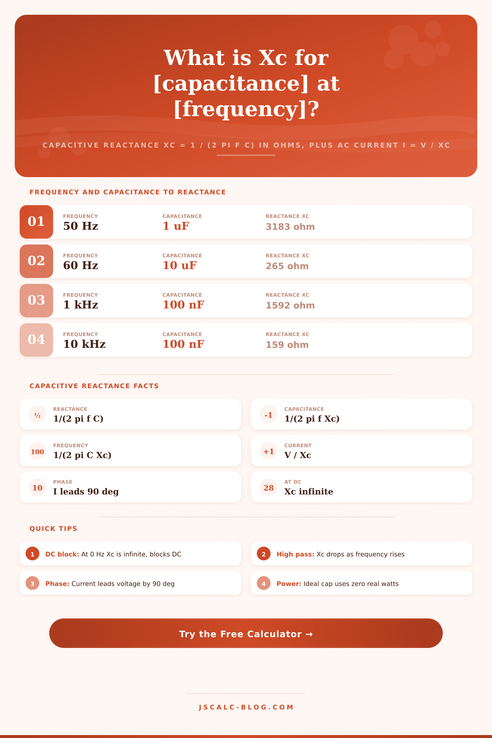
Put in a 1 microfarad capacitor at 50 hertz and the calculator spits back about 3183 ohms. Push the frequency up to 1 kilohertz and the same part drops down to around 159 ohms. The equation Xc = 1 / (2 pi f C) connects three variables. Given any two, you get the third.
You can use the solve for selector to choose which variable you want to find. Select reactance and you put in the frequency and capacitance and instantly have the reactance right there. Select capacitance and the tool swaps to C = 1 / (2 pi f Xc), letting you answer that all too frequent design problem: What capacitance do I need to get a certain reactance at this frequency?
Select frequency and it calculates the f = 1 / (2 pi C Xc) point where a particular capacitor reaches the selected reactance. That’s the basis for setting a filter corner. The input fields never conflict, so the one being solved for is disabled.
With the reactance value in hand, Ohm’s law for ac yields the current from I = V / Xc. Simply enter the RMS voltage that you supply and the calculator computes the current. It does so in such a way that the displayed number remains reasonable, using either amps, milliamps, or microamps.
The other result of equal importance is the phase. For an ideal capacitor, the current will lead the voltage by 90 degrees, or a quarter of a cycle. The tool displays this as a phase of -90 degrees. Since the voltage and current are 90 degrees apart, there is no dissipation of energy, just storage and return. Therefore, the real power is zero watts. This means that coupling and bypass capacitors can conduct large current with little to no warming.
Consider an audio stage operating at 10 kilohertz with a 100 nanofarad coupling capacitor. Use Xc = 1 / (2 pi f C) to plug in the numbers. 2 pi f, the angular frequency, is approximately 62832 radians per second. Multiply that by 100 nanofarads and invert for approximately 159 ohms. With a 1 volt signal across this, we have current equal to I = 1 / 159 or approximately 6.3 milliamps with the current leading the voltage by 90 degrees.
Lowering the frequency down to 1 kilohertz increases the reactance by a factor of ten to around 1592 ohms. Therefore, the same capacitor allows much less low frequency signal through. This frequency dependency is precisely why capacitors are used as DC blocks and also make them high pass elements.
The results is presented on four cards. The first is the reactance card, which shows Xc in ohms, kilohms, or megohms, depending on the size of the capacitor. The second is the current card: I = V / Xc if you input a voltage; it warns you if you don’t. The third card shows phase, reminding you that the current leads and always stays at the same angle (fixed at -90 degrees). The fourth card repeats whatever the requested unknown was, whether it’s capacitance or frequency in reverse-mode.
You get a nice note saying “ideal capacitor dissipates no real power.” Then there’s a breakdown panel listing all the numbers that were substituted one-by-one. In other words, it lets you check your own hand calculations, too.
The calculator takes frequency (hertz, kilohertz, megahertz) and capacitance (microfarads, nanofarads, or even picofarads), mixing different scales used in real circuits. The calculator converts all inputs to base units internally. One megahertz is a million hertz. One kilohertz is 1000 hertz. A microfarad is a million picofarads or 1000 nanofarads.
The reference tables walk through reactance for a 1 microfarad capacitor across a full frequency sweep. Then they show the drop off in reactance of the capacitor with higher values at both 1 kHz and 100 kHz. A broad table compares frequency vs. Capacitance against reactance, phase, current at 10 volts, and a typical application note.
Real world scenarios are loaded as presets which calculate instantly. For instance, a DC blocking capacitor; a snubber at 100 kilohertz; a mains filter cap at 50 hertz; an RF bypass at 1 megahertz; a power factor capacitor at 60 hertz; an audio coupling cap at 10 kilohertz; a decoupling cap and a switching supply output capacitor. To show that the reverse works, there are two more presets. One calculates the capacitance for 1 kilohertz at 1000 ohms. And the other calculates the frequency of a 1 microfarad part at 159 ohms.
The fastest method to develop some sense of how reactance changes is to start from one of the presets and nudge the values. A dropped decimal is a quiet wrecking ball for any power supply, coupling network or filter. This calculator covers both design and analysis with one equation: Xc = 1/(2 pi f C), and all its rearrangements, plus current relationship of I=V/Xc all in one space. Those are the two anchors.
A capacitor does not conduct DC because at zero hertz the reactance is infinity. The higher the frequency, the lower the reactance. This means that as frequency rises, more and more AC is passed, but the current always lags the voltage by 90 degrees. Select a preset, adjust the input, and read the cards to get a breakdown of trustworthy numbers within seconds.
You should of used this sooner. It’s moddern technology.