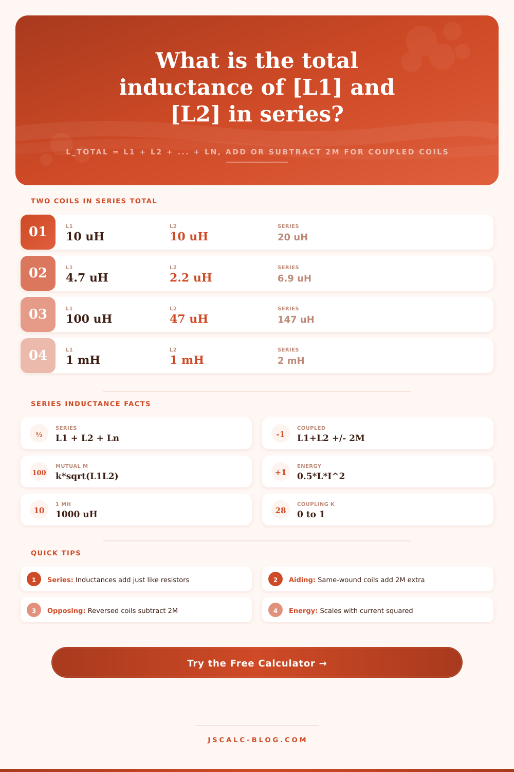
Series Inductance Calculator
Add inductors connected in series with L_total = L1 + L2 + ... + Ln, then account for mutual coupling between two adjacent coils using L = L1 + L2 +/- 2M where M = k times the square root of L1 times L2, and finish by finding the energy stored in the equivalent inductor from E = one half times L times current squared.
⚡Choose a Mode
🎯Real Series Coil Presets
📝Inductance Inputs
All inductance fields use this unit and relabel to match.
How many coils are wired end to end in the chain.
First coil in the series chain.
Second coil in the series chain.
Third coil, used when 3 or more are selected.
Fourth coil, used when 4 or more are selected.
Fifth coil, used when 5 or more are selected.
Sixth coil, used when 6 are selected.
First coupled coil L1 in the pair.
Second coupled coil L2 in the pair.
0 is no coupling, 1 is perfect coupling.
Winding sense sets whether M adds or subtracts.
Steady current used for stored energy E.
Controls rounding on every result card.
🔢Formula Snapshot
📋Two Coils in Series Reference
| Inductor L1 | Inductor L2 | Series Sum L1 + L2 | Reads As |
|---|---|---|---|
| 10 µH | 10 µH | 20 µH | Doubled |
| 4.7 µH | 2.2 µH | 6.9 µH | E12 pair |
| 100 µH | 47 µH | 147 µH | Mixed values |
| 220 µH | 330 µH | 550 µH | Power coils |
| 68 µH | 33 µH | 101 µH | Near 100 µH |
| 1 mH | 1 mH | 2 mH | Doubled mH |
| 2.2 mH | 4.7 mH | 6.9 mH | Crossover |
| 470 µH | 100 µH | 570 µH | Filter stack |
📊Coupling Coefficient Effect (Two 10 µH Coils)
| Coupling k | Mutual M | Aiding + 2M | Opposing - 2M | Coupling Type |
|---|---|---|---|---|
| 0.0 | 0 µH | 20 µH | 20 µH | None |
| 0.1 | 1 µH | 22 µH | 18 µH | Very loose |
| 0.25 | 2.5 µH | 25 µH | 15 µH | Loose |
| 0.5 | 5 µH | 30 µH | 10 µH | Moderate |
| 0.7 | 7 µH | 34 µH | 6 µH | Fairly tight |
| 0.9 | 9 µH | 38 µH | 2 µH | Tight |
| 1.0 | 10 µH | 40 µH | 0 µH | Perfect |
📏Inductance Unit Conversions
| Unit | Equals | In Henries | Typical Use |
|---|---|---|---|
| 1 H | 1000 mH | 1 H | Mains chokes, filters |
| 1 mH | 1000 µH | 0.001 H | Audio, power supplies |
| 1 µH | 0.001 mH | 0.000001 H | RF, switching coils |
| 1 nH | 0.001 µH | 0.000000001 H | PCB trace, VHF |
| 100 µH | 0.1 mH | 0.0001 H | Buck converter coil |
| 4.7 mH | 4700 µH | 0.0047 H | Woofer crossover |
🗃Series String Comparison Grid
| Configuration | Coils | Each Value | Coupling k | Total L | E at 2 A |
|---|---|---|---|---|---|
| Two chokes | 2 | 10 µH | 0 | 20 µH | 0.04 mJ |
| RF 3-coil string | 3 | 10/22/47 µH | 0 | 79 µH | 0.158 mJ |
| Coupled aiding | 2 | 10 µH | 0.5 | 30 µH | 0.06 mJ |
| Coupled opposing | 2 | 10 µH | 0.5 | 10 µH | 0.02 mJ |
| Two buck coils | 2 | 1 mH | 0 | 2 mH | 4 mJ |
| Four power coils | 4 | 220 µH | 0 | 880 µH | 1.76 mJ |
| Tuned trap pair | 2 | 100 µH | 0 | 200 µH | 0.4 mJ |
| Tight coupled | 2 | 10 µH | 0.9 | 38 µH | 0.076 mJ |
| Audio crossover | 2 | 2.2/1 mH | 0 | 3.2 mH | 6.4 mJ |
| E12 small pair | 2 | 4.7/2.2 µH | 0 | 6.9 µH | 0.0138 mJ |
⚙Formula Breakdown
💡Series Inductor Design Tips
Got a box of inductors? Need a certain value that isn’t in the box? Wire ’em all together and hope for the best, right?
One of the best ways by far (and the one with the simplest math) is to stack the coils up in series. Inductance add up like resistance: straight up. You grab your first coil, add the next, continue along the chain. Sum the parts and there you go, that’s your total.
How to Add Inductors in Series
It’s the simplicity of this math that gets engineers stringing things up in series in the first place; they’re trying to reach a particular value somewhere between available component. That’s what the calculator above does quickly, but then it flags that one gotcha that typicaly catches the careless among us at some point in our lives.
When inductors are wired end-to-end, the same current flow through all turns of each coil in the chain. The voltage across any inductor is proportional to inductance multiplied by the rate of change of current. So total voltage drop is the sum of the individual drops: the equivalent inductance is simply $L_1 + L_2 + \dots + L_n$.
You can also mix units; the tool will let you work in henries, millihenries or microhenries without losing track of decimal points. Millihenries makes sense for a large coil like an audio crossover part. Microhenries make sense for a small coil like a switching converter coil. The right unit keeps your numbers readable and saves you from counting them wrong which prevents you from wasting an afternoon trying to find the error.
When you put two coils too close together, that’s where the trouble begins. A magnetic field doesn’t simply dissapears at physical boundary of its associated component. One coil’s flux can thread another, and if it does, they’re coupled. This mutual inductance is represented as M, and it depends on the orientation of each coil’s windings relative to others, plus how closely they share the available space.
The tighter the coupling, the higher value of M; the lower the coupling, the closer it’s set to zero. For loosely-spaced discrete inductors mounted on a board, the value of k (the coupling coefficient) is typicaly very low, which means we needn’t worry about it. But if you pack components tight on a power supply or if you wind your own chokes, k become quite important. As table of references on the page shows, going from a loose coupling to a tight one causes a dramatic change in behavior.
Now, how does that help or hurt? Turns out that depends entirely on orientation. If both fields strengthen each other, then you’ve got aiding. The total inductance becomes $L_1 + L_2 + 2M$, which is more than the simple sum. Flip over one of those coils and the fields will be opposed. You now have coils in opposition, which equals $L_1 + L_2; 2M$. Total decreases dramatically.
For example, if I have two 10-microhenry coils with a modest coupling of 0.5, aiding increases the result to 30 microhenries, while opposing reduces it to 10. A three-to-one swing in performance for the very same components, all because of whether or not you plug ‘em in one direction rather than another. This is a tiny bit of physics with huge electrical effects.
Lastly, let’s talk energy. \(5 \times L \times I^2\). But it’s not just some academic discussion. When you break the current, where does all of that stored energy go? When you’re designing a switcher circuit, you want to know how much energy gets trapped on that series string so you can size your clamp circuits or snubber diodes.
Twice the current means four times the energy; so current rating matter as much as inductance value. Hit that target \(L\) dead-on, but one coil in that series chain saturate at a low current and the whole design collapses. The weak link sets the limit.
Tweak the numbers for your board and see how various configs behave with the presets. It’s not just adding up parts, it’s about controlling the flow and managing energy.