Series Resistance Calculator
Add up to eight resistors in series with Rtotal = R1 + R2 + ... + Rn, then find the total current I = V divided by Rtotal that flows through every part, the voltage drop Vi = I times Ri across each resistor, the voltage distribution percentage, and the power Pi = I squared times Ri each one dissipates. You can also solve for a missing resistor needed to reach a target total.
⚡Choose a Mode
🎯Real Series Circuit Presets
🔌Supply and Resistor Inputs
DC source driving the whole series string.
Missing R = target minus the sum of the others.
Unit applied to the target total above.
First resistor. Leave any resistor at 0 to skip it.
Second resistor in the chain.
Third resistor. Set to 0 if unused.
Fourth resistor. Set to 0 if unused.
Fifth resistor. Set to 0 if unused.
Sixth resistor. Set to 0 if unused.
Seventh resistor. Set to 0 if unused.
Eighth resistor. In missing mode, R8 is the unknown to solve.
Controls rounding on every result card.
🔢Formula Snapshot
📋Series Circuit Rules and Properties
| Quantity | Series Behavior | Formula | Plain Meaning |
|---|---|---|---|
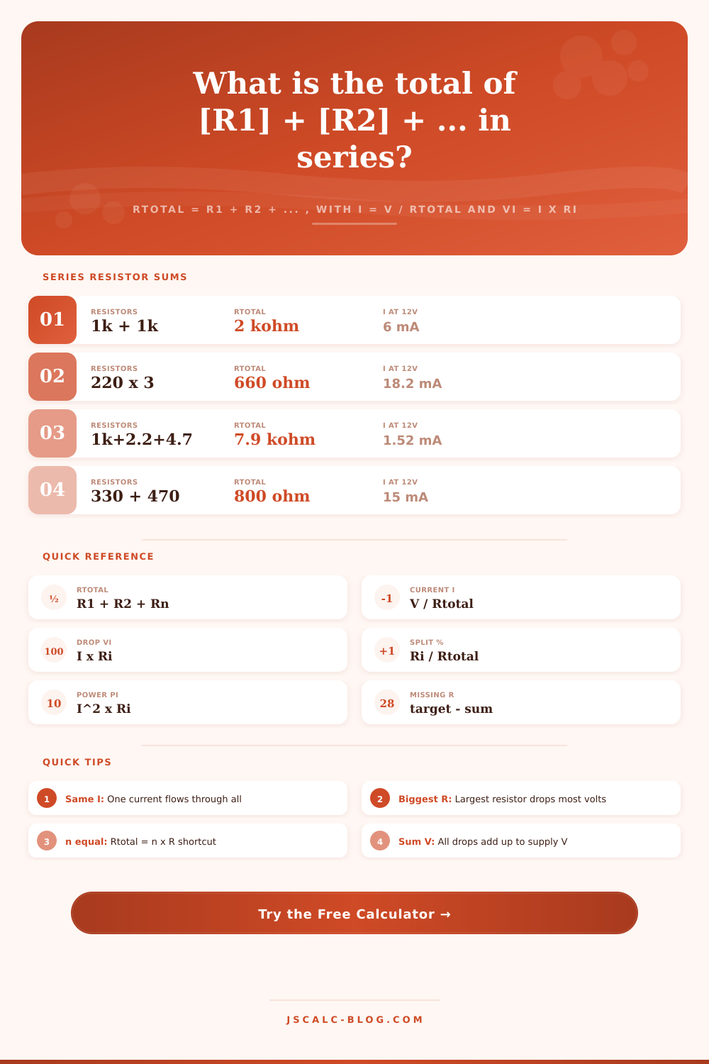
| Total resistance | Resistances add | Rt = R1 + R2 + ... + Rn | Always larger than any single R |
| Current | Same everywhere | I = V / Rt | One path, one current value |
| Voltage drop | Divides by resistance | Vi = I × Ri | Bigger R takes a bigger share |
| Voltage sum | Drops add to supply | V = V1 + V2 + ... + Vn | Kirchhoff voltage law |
| Power per part | Splits by resistance | Pi = I² × Ri | Bigger R heats up more |
| Total power | Sum of each part | P = V × I = I² × Rt | All heat comes from the source |
| Distribution | Proportional share | Ri / Rt × 100 | Percent of the supply on each R |
📏Equal Resistor Shortcut (n x R)
| Count n | Each Resistor | Rtotal = n x R | I at 12 V | Drop on Each |
|---|---|---|---|---|
| 2 | 100 ohm | 200 ohm | 60 mA | 6.0 V |
| 3 | 220 ohm | 660 ohm | 18.2 mA | 4.0 V |
| 4 | 470 ohm | 1.88 kohm | 6.38 mA | 3.0 V |
| 5 | 330 ohm | 1.65 kohm | 7.27 mA | 2.4 V |
| 6 | 1 kohm | 6 kohm | 2.0 mA | 2.0 V |
| 8 | 150 ohm | 1.2 kohm | 10 mA | 1.5 V |
| 10 | 100 ohm | 1 kohm | 12 mA | 1.2 V |
📊Voltage Distribution Example (12 V Supply)
| Resistor | Value | Share Ri / Rt | Voltage Drop | Power at I |
|---|---|---|---|---|
| R1 | 1 kohm | 12.66 % | 1.52 V | 2.31 mW |
| R2 | 2.2 kohm | 27.85 % | 3.34 V | 5.08 mW |
| R3 | 4.7 kohm | 59.49 % | 7.14 V | 10.85 mW |
| Total | 7.9 kohm | 100 % | 12.0 V | 18.23 mW |
| Current I | 1.519 mA | same in all | V / Rt | I² × Rt |
| Biggest drop | R3 = 4.7 kohm | largest R | 7.14 V | most heat |
🔄Series vs Parallel Contrast
| Property | Series Connection | Parallel Connection |
|---|---|---|
| Total resistance | Rt = R1 + R2 + ... | 1/Rt = 1/R1 + 1/R2 + ... |
| Compared to parts | Larger than any resistor | Smaller than any resistor |
| Current | Same through all parts | Splits between branches |
| Voltage | Divides across parts | Same across all branches |
| Two equal R | 2R total | R / 2 total |
| One part opens | Whole circuit stops | Other branches keep working |
| Common use | Voltage dividers, strings | Load sharing, power rails |
🗃Series Combination Comparison Grid
| Combination | Rtotal | I at 12 V | Biggest Drop | Total Power | Note |
|---|---|---|---|---|---|
| 1k + 1k | 2 kohm | 6.00 mA | 6.0 V each | 72 mW | Equal 50 / 50 split |
| 220 + 220 + 220 | 660 ohm | 18.18 mA | 4.0 V each | 218 mW | Three equal thirds |
| 1k + 2.2k + 4.7k | 7.9 kohm | 1.52 mA | 7.14 V (4.7k) | 18.2 mW | Divider chain |
| 330 + LED (approx 470) | 800 ohm | 15.0 mA | 7.05 V (470) | 180 mW | LED drop modeled |
| 470 x 4 | 1.88 kohm | 6.38 mA | 3.0 V each | 76.6 mW | Even string of four |
| 100 x 10 | 1 kohm | 12.0 mA | 1.2 V each | 144 mW | Ten equal steps |
| 150 + 100 | 250 ohm | 48.0 mA | 7.2 V (150) | 576 mW | Uneven two-part |
| 47 + 47 (ballast) | 94 ohm | 127.7 mA | 6.0 V each | 1.53 W | Current-limit stack |
| 10 + 10 | 20 ohm | 600 mA | 6.0 V each | 7.2 W | High-current heaters |
| 1M + 1M | 2 Mohm | 6.0 uA | 6.0 V each | 72 uW | High-impedance divider |
⚙Formula Breakdown
💡Series Design Tips
A series connection is simply you placing components in line with each other. In this case, all of parts become a longer part, an extended obstacle that electrons has to get around. Electricity does not care what you want; it just cares about the overall resistance. You plug in your values and let calculator do the rest. It will then tell you precisely how many volts go where and which component has to shed how much heat.
In a series string, there’s only one way for current to go. It can’t jump over first resistor and get to second. And it can’t take short cuts past others. The path is unique so the amount of resistance the whole thing has is simply addition of each separate resistor. No fancy equations required here. A 1 kilohm plus a 2 kilohm in series gives circuit a total of 3 kilohms. That total determine how much current flows through entire circuit. The supply voltage divided by total resistance equates to current.
How Series Circuits Work
All components in the chain recieve the same exact current. Larger resistors hog more of the juice. Series circuits is predictable because of this consistency. They’re also unforgiving. Different voltages are distribute differently. The current remains constant. But, it doesn’t mean that every resistor will get the same amount of voltage drop. That depends on its size compared to other resistor.
The tool shows you the percentages of how much of supply voltage is distributed where. When you put a large resistor like a 4.7 kilohm next to a small one like 100 ohms, big guy will take almost whole supply voltage. The little dude will see almost no voltage drop at all. Check it out with Ohm’s law applied to both components. Viewing it as a percentage makes it easier to understand what each piece of resistance is doing.
The highest is taking the most voltage and running hottest. That is important if you are choosing wattage rating. The same proportional rule apply to power dissipation. Power dissipated in heat is directly proportional to resistance, because current is constant. So if one resistor is the highest value, then that’s the biggest resistor doing the most work. That means it will also produce most heat.
A good tip: Always size the big component first. If you use a power resistor with a rating that is too small for largest load, it would of burn out before smaller resistors even get hot. You can see how this breaks down in calculator. It lets you know who needs bigger package. Sometimes we assume they will share equally but that is not true if there are large differences between them.
But then there’s that situation where you have a standard value on hand but are looking for missing piece to reach your target total. That’s a common occurrence during design when you want to add some component to an existing circuit and only have a standard value available. In that case you are reverse engineering your way to a solution. The missing resistor mode does just that: it subtracts known components from desired total.
So if you have 3.2k ohms installed and you want 10 kilohms total, it can tell you exactly what you’re missing so you can get precisely there. That’s a useful feature for tweaking LED current or trimming down a voltage divider without having to purchase several prototype boards.
Once you understand how things behave in series, it starts to change the way you think about reliability. One thing about a parallel circuit: if one branch fails others continue functioning. With a series circuit, any open connection shuts down everything. It becomes a single point of failure throughout entire chain. That’s the trade-off you make with simplicity and fragility in design of systems.
You go with series connections because they will divide voltage naturaly and restrict current predictably. But you’re accepting that there will be a fragility to continuity. The tool lets you balance those out by visualizing impact on power loss and current draw in real-time. Control is the end game. You send some safe current through that LED and certain voltage to that sensor.
Use arithmetic precision to dial it all in with resistors in series. You understand how changes rippled through circuit because you thought of it as a single thing instead of a bag of parts. Not only do resistors alter one value; they shift the power load and voltage distribution on each component. That’s what makes a good design hold up in the real world vs it is merely functional. The calculator provides the numbers. Knowing how those things relate to each other assures you that it will stand up to reality.