Series-Parallel Resistor Network Calculator
Build a mixed network of a series resistor combined with a parallel bank of up to four resistors. This tool finds the total resistance with Rtotal = Rseries + Rparallel, then computes total current I = V / Rtotal, dissipated power P = V squared / Rtotal, the voltage across the parallel bank, and the individual branch currents and power.
🔌Choose a Network Topology
Series then Parallel: one series resistor feeds a parallel bank (bank A). Parallel then Series is the same math with the order flipped. Two Parallel Banks puts bank A in series with a second parallel bank (bank B). Leave a branch at 0 to skip it.
🎯Real Network Presets
📌Network Values
DC source applied across the whole network.
In series with the parallel bank (set 0 to omit).
First resistor in the parallel bank A.
Second parallel branch (set 0 to skip).
Third parallel branch (set 0 to skip).
Fourth parallel branch (set 0 to skip).
Used only in Two Parallel Banks mode.
Second branch of bank B (set 0 to skip).
Controls rounding on every result value.
🔢Formula Snapshot
📋Series vs Parallel Rules
| Quantity | In Series | In Parallel | Key Point |
|---|---|---|---|
| Resistance | Rs = R1 + R2 + ... | 1/Rp = 1/R1 + 1/R2 + ... | Series adds, parallel reciprocals |
| Current | Same through all | Splits between branches | Series shares one current |
| Voltage | Adds up to source | Same across all branches | Parallel shares one voltage |
| Total R vs parts | Larger than any part | Smaller than smallest part | Parallel always lowers R |
| Two equal R | 2R | R / 2 | Doubling flips both ways |
| N equal R | N x R | R / N | Handy shortcut for equal banks |
| Open branch | Breaks the whole path | Others keep working | Parallel is fault tolerant |
| Power split | P higher on larger R | P higher on smaller R | P = V squared / R in parallel |
📊Two-Resistor Parallel Quick Values
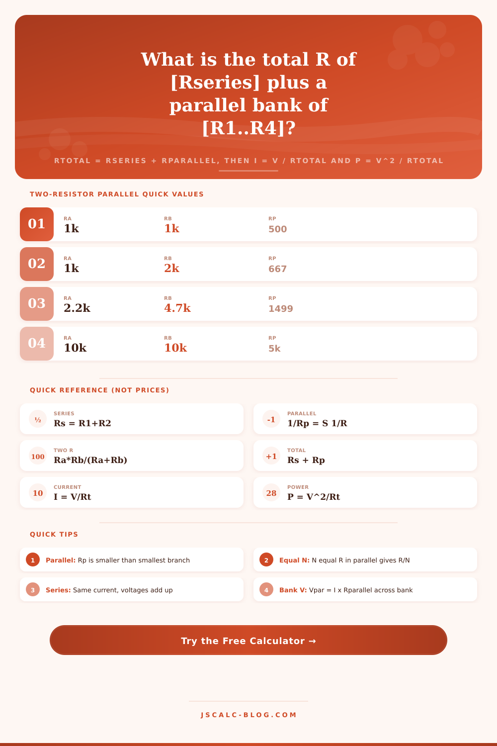
| Ra | Rb | Rp = Ra Rb / (Ra + Rb) | Note |
|---|---|---|---|
| 1 k | 1 k | 500 Ω | Two equal, halved |
| 1 k | 2 k | 667 Ω | Below smaller value |
| 2.2 k | 4.7 k | 1499 Ω | Common E24 pair |
| 10 k | 10 k | 5 k | Equal, halved |
| 100 Ω | 100 Ω | 50 Ω | Power sharing pair |
| 330 Ω | 470 Ω | 194 Ω | LED ballast pair |
| 1 k | 10 k | 909 Ω | Big ratio, near 1 k |
| 4.7 k | 4.7 k | 2.35 k | Equal, halved |
🧩Equivalent Resistance of Common Combos
| Combination | Type | Working | Result |
|---|---|---|---|
| 1 k + 1 k | Series | 1000 + 1000 | 2 k |
| 1 k, 1 k | Parallel | 1000 / 2 | 500 Ω |
| Three 1 k | Parallel | 1000 / 3 | 333.3 Ω |
| Four 1 k | Parallel | 1000 / 4 | 250 Ω |
| 100 + (1 k || 1 k) | Mixed | 100 + 500 | 600 Ω |
| 1 k + (2.2 k || 4.7 k) | Mixed | 1000 + 1499 | 2499 Ω |
| 10 k, 4.7 k | Parallel | 10k x 4.7k / 14.7k | 3197 Ω |
| 220 + (330 || 470) | Mixed | 220 + 194 | 414 Ω |
🔌Topology Comparison Grid
| Topology | Formula | Example R | Rtotal | Total I at 12 V | Note |
|---|---|---|---|---|---|
| Series then Parallel | Rs + Rp | 100 + (1k,2.2k,4.7k) | 699.8 Ω | 17.1 mA | Series drop then split |
| Parallel then Series | Rp + Rs | (1k,2.2k) + 100 | 787.5 Ω | 15.2 mA | Same math, order flipped |
| Two Parallel Banks | Rp1 + Rp2 | (1k,2.2k)+(1k,1k) | 1187 Ω | 10.1 mA | Two banks in series |
| Single Series | R1 + R2 | 1k + 2.2k | 3200 Ω | 3.75 mA | No parallel branch |
| Single Parallel | 1 / (S 1/R) | 1k, 1k, 1k | 333.3 Ω | 36 mA | No series resistor |
| Ladder (2 rungs) | Rs + (R || rest) | 1k + (2.2k || 4.7k) | 2499 Ω | 4.8 mA | Cascade of series and shunt |
| Balanced Bank | Rs + R/N | 0 + four 1k | 250 Ω | 48 mA | Equal branches share load |
| LED String Net | Rs + (R || R) | 330 + (470 || 470) | 565 Ω | 21.2 mA | Ballast plus dual string |
⚙Formula Breakdown
💡Design Tips
The reason most electronics projects fall apart: “I thought it was all in parallel! But actualy some of it’s in series…” In real life, few circuits are as pure as what we read about in books. More often than not, it’s a load bank fed by a ballast resistor, or a set of sensor dividing down a supply rail. Trying to do the math in your head quick becomes a mess.
This tool avoids that by taking out the fiddly business of reducing the combination. It gives you the full picture at a glance, including total resistance, power, current, and branch currents. Plug in the numbers relevant to your project, and let it do the work for you.
How to Use This Resistor Calculator
In other words: all resistor networks boils down to two moves, and in the correct order. Series resistors (one current path shared between them) simply add. Easy arithmetic. Parallel resistors (bridge the same two nodes), combine via reciprocals. This is where it throws people off. It’s an ugly formula, but it has a nice clean intuition: adding a path means current can flow more easly, so combined resistance is always less then the smallest link.
If you nest things… Such as a parallel bank behind a series resistor, for example; you just have to do the bank first, then the rest. That collapses the bank, and then you add on the series component. You don’t even have to worry about algebra mistakes because the calculator nests all that for you.
For precisely two resistors there’s a neat shortcut to the parallel rule. Simply take their product and divide by their sum. It is the product over the sum. What if you have four 1k resistor in parallel? Yep, that’ll be 250 ohms. A pair of 1k resistors in parallel? Yep, that’s 500 ohms. See how that works? If you have n identical resistors in parallel, then you get R/n.
So if I know the answer should of been 250 ohms, but my calculation came up with 4000 ohms; well, something went wrong. Parallel can’t increase resistance. It will always decrease it. That’s what many people forget as they speed-read through math.
Ohm’s law does the rest: voltage over the total equivalent resistance equals the total current the source pushes through it. That tells you if your power supply can handle the load. Voltage squared over resistance give you the total power delivered. That tells you whether your resistors will be smoking hot. Those are the figures that make or break projects. The tool plainly displays those numbers in scaled, human-readable units, saving you from having to count zeros. It takes the abstract and shows real-world limits of what your hardware can do.
How does voltage get divided? That’s where it gets interesting with a mixed network. It acts like a voltage divider between the series resistor and the parallel bank. The amount of voltage dropped across the series component depend on its resistance. Then the remainder is applied across the bank. Since all the branches has the same voltage applied, each will pull whatever current their individual resistance allows. So, smaller branches pull more, and those dissipate more power.
Why is that important? Well, you need to size things correctly. A small one in a parallel bank can potentially take the brunt of the load while everyone else sits there cool. You’ll see that breakdown in the section to ensure no single part is being overloaded.
The interface allows for toggling among the most typical of these layouts. The classic ballast shape is series followed by parallel. Flip it around with parallel then series. Flips the order but keeps the math identical. Two parallel banks line up two sets end-to-end, which is common if you have an array of sensor or LEDs. Changing between them doesn’t alter the physics; it merely changes what the tool calls things. Parallel decreases resistance, while series increases it. Your load is the combination. It’s a good way of exploring design decisions without having to solder anything first.
If you’re doing this manually, units are a drag. You have to make sure that your ohms or your kilohms or your megohms all line up when you put things together. When you input 100 into one field and 10k into another, the tool does the conversion for you automaticly. And you can set branches to zero and bypass them completely. That instantly transforms a four-input bank into a two-branch setup. It keeps the interface tidy but allows you to model as much (or as little) complexity as necessary.
Hand calculations fail on mixed networks. You can easily multiply when you need reciprocals; you can overlook that only half the supply voltage appear across the parallel bank. This calculator will do the steps in the right sequence, print the substituted values from line to line, and turn a fiddly reduction exercise into something you know came out right.
Use the presets to see how the values play off each other, then adjust until they match your design. It is not just about getting the number, but seeing where that current goes and what difference it makes. For a bias network check, or for learning circuit analysis, use the preset and twist.