Resistor Color Code Calculator
Decode 4-band, 5-band, and 6-band resistor color codes into resistance in ohms, tolerance percentage, minimum and maximum value range, and the temperature coefficient, with a full band-by-band breakdown.
🎯Common Resistor Presets
🌈Band Colors
Disabled for 4-band resistors.
Only used for 6-band resistors.
🔢Decoding Snapshot
🌈Full Resistor Color Chart
| Color | Digit | Multiplier | Tolerance | Temp Coeff |
|---|---|---|---|---|
| Black | 0 | ×1 | – | – |
| Brown | 1 | ×10 | ±1% | 100 ppm/K |
| Red | 2 | ×100 | ±2% | 50 ppm/K |
| Orange | 3 | ×1k | – | 15 ppm/K |
| Yellow | 4 | ×10k | – | 25 ppm/K |
| Green | 5 | ×100k | ±0.5% | 20 ppm/K |
| Blue | 6 | ×1M | ±0.25% | 10 ppm/K |
| Violet | 7 | ×10M | ±0.1% | 5 ppm/K |
| Gray | 8 | ×100M | ±0.05% | 1 ppm/K |
| White | 9 | ×1G | – | – |
| Gold | – | ×0.1 | ±5% | – |
| Silver | – | ×0.01 | ±10% | – |
| None | – | – | ±20% | – |
📐E-Series Standard Values
| Series | Tolerance | Values Per Decade | Example Values |
|---|---|---|---|
| E6 | ±20% | 6 | 10, 15, 22, 33, 47, 68 |
| E12 | ±10% | 12 | 10, 12, 15, 18, 22, 27, 33 ... |
| E24 | ±5% | 24 | 10, 11, 12, 13, 15, 16, 18 ... |
| E48 | ±2% | 48 | 10.0, 10.5, 11.0, 11.5 ... |
| E96 | ±1% | 96 | 10.0, 10.2, 10.5, 10.7 ... |
| E192 | ±0.5% and tighter | 192 | 10.0, 10.1, 10.2, 10.4 ... |
🌡Tolerance and Temp Coefficient Reference
| Band Color | Tolerance | Temp Coeff | Typical Use |
|---|---|---|---|
| Brown | ±1% | 100 ppm/K | Precision film resistors |
| Red | ±2% | 50 ppm/K | Metal film general use |
| Green | ±0.5% | 20 ppm/K | Tight tolerance circuits |
| Blue | ±0.25% | 10 ppm/K | Instrumentation and audio |
| Violet | ±0.1% | 5 ppm/K | Reference and metrology |
| Gold | ±5% | – | Standard carbon and film |
| Silver | ±10% | – | Low-cost carbon film |
| None | ±20% | – | Legacy carbon composition |
🗂Band Position and Comparison Grid
| Bands | Band 1 | Band 2 | Band 3 | Multiplier | Tolerance | Temp Coeff |
|---|---|---|---|---|---|---|
| 4-band | Digit 1 | Digit 2 | – | × factor | ± percent | – |
| 5-band | Digit 1 | Digit 2 | Digit 3 | × factor | ± percent | – |
| 6-band | Digit 1 | Digit 2 | Digit 3 | × factor | ± percent | ppm/K |
| 220 Ω 4-band | Red (2) | Red (2) | – | Brown ×10 | Gold ±5% | – |
| 4.7k 5-band | Yellow (4) | Violet (7) | Black (0) | Brown ×10 | Brown ±1% | – |
| 10k 6-band | Brown (1) | Black (0) | Black (0) | Red ×100 | Brown ±1% | Brown 100 |
⚙Full Formula Breakdown
💡Practical Resistor Tips
When you’re working in your garage and pull out a beige resistor from your project box only to discover its label has worn away, there’s a moment of panic, all you’re left with is what appears to be an abstract work of art in colored stripes. It makes sense once you stop being confused by it. It was made as efficiently as possible during manufacturing. Even if printed small or under less than optimal light in a workshop, the colors stands out. Once you have the knowledge, you can interpret it: a confusing blob becomes a specific spec.
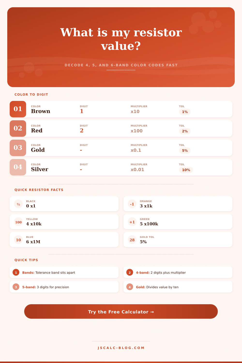
It is all about Digit Bands. Multiplier Band: How do they work? Consider the first couple of stripes as “significant figures.” A brown stripe equals 1. A red stripe = 2. A white stripe = 9. A black stripe = 0. These digits combines to create the base resistance value.
How to Read Resistor Color Codes
Then there’s the multiplier band. That’s how many zeros you tack on. Silver means divide by 100, and gold means divide by ten. That gives us fractional values less than an Ohm. And we need those fractional values in current sensing applications.
If you’re going outside the normal four band resistors, then precision is another consideration. For example, for things like sensitive measuring instruments or audio gear, you probably go up to 5 or 6 bands. If it’s a five band resistor, the third band will be an additional digit. Instead of having only two significant figures, you now have three. That means you can have a tighter tolerance. The actual resistance will be even closer than what’s printed on the resistor.
Once you plug in the colors, a calculator does the math for you. No more memorizing that green represents either a five or a six. And it also splits out the min and max range depending on the tolerance.
It’s in the sixth band and describes the rate at which the resistance changes with temperature. One hundred parts per million per Kelvin change is indicated by a brown stripe. Sounds like nothing, but when you consider that a resistor may be twenty degrees above ambient, it’s enough to destroy calibration in high-precision analog circuits.
Metal film resistors are better choices than carbon composition types. Again, it’s not just the color code but what’s inside the resistor that makes the difference. So, how do you choose the correct part? That depends on what is needed and what you are willing to pay.
For example, if you are building a simple current limiter for an LED then don’t use a 1% tolerance resistor. The LED tolerances vary widely by manufacturer. If you need exact values for things like a filter circuit or a voltage reference, loose tolerance causes distortion and noise.
One color table compares parts to their corresponding ppm/K values making it easy to see which color bands corresponds to better grade parts. People get tripped up because they are reading the bands out of sequence. There’s usually a small gap between the tolerance band and the rest of them. That’s the one on the right. Silver, gold… those is some common ones here because they never show up as digits. If you see gold over there on the left, your answer is going to be off by a factor of ten.
Remember that separation when you’re not sure what the color means. Brown might look like black. Brown might look like gray on a faded resistor. When in doubt, check the actual size of the resistor. Loose tolerances are rarely used for tiny 0805 surface mount part. That manufacturing process has precision built into it.
The trick isn’t to try to memorize a chart but rather interpret meaning from reading these numbers. How accurate? Are they stable? What kind of thermal performance do they have? Look at those stripes as an engineers’ compromise that occurred way back in time before you purchased the component. Once you start to learn what to look for, that pile of random components stops looking like a puzzle and starts looking like a toolkit.
What you see is a set of tools. All you have to do is read the bands from left to right. Let the numbers point you in the right direction and ignore the rest. You should of checked the colors first. Actualy, it’s more easy if you use a tool rather than just guessing based off the visual. I recieved a bad one yesterday that was quite luxurius looking but wrong.