RC High Pass Cutoff Frequency Calculator
Find the -3 dB corner of a resistor-capacitor high-pass filter with fc = 1 / (2 x pi x R x C). Solve for the resistor or capacitor when you have a target cutoff, read the attenuation in dB at any test frequency, and get the time constant tau and the +20 dB per decade rising slope for AC coupling and DC blocking.
⚡Real High-Pass Presets
📌Filter Inputs
Pick the unknown; the fields it needs stay active below.
Total resistance the coupling capacitor sees to ground.
The series AC-coupling capacitor value.
Only used when solving for R or C.
Gain in dB is reported at this frequency.
Controls rounding on every result card.
🔢Formula Snapshot
⚙Formula Breakdown With Your Numbers
📊Frequency Ratio vs High-Pass Attenuation
| f / fc | Magnitude |H| | Gain (dB) | Meaning |
|---|---|---|---|
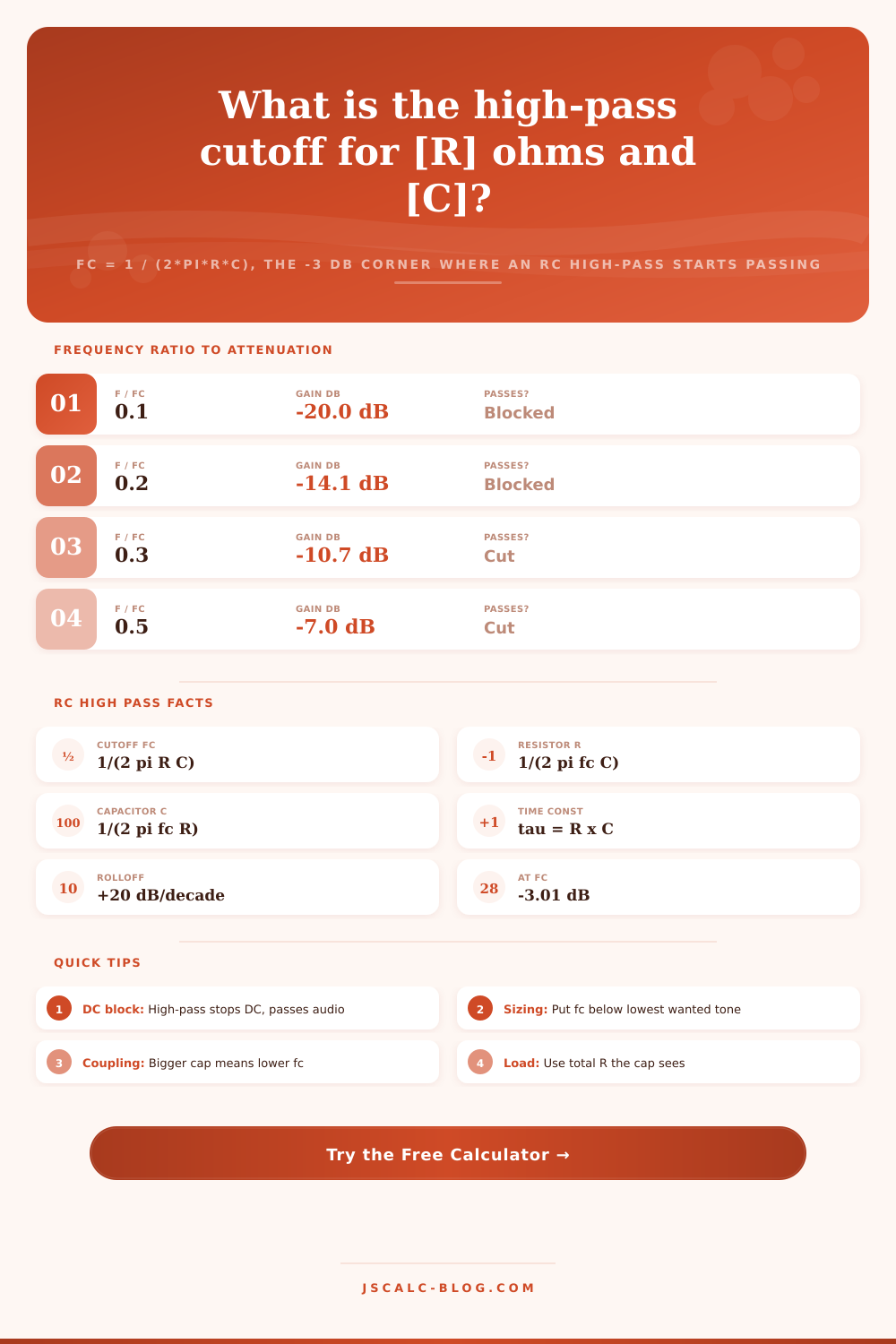
| 0.1 | 0.0995 | -20.04 dB | Strongly blocked |
| 0.2 | 0.196 | -14.15 dB | Blocked |
| 0.3 | 0.287 | -10.84 dB | Heavily cut |
| 0.5 | 0.447 | -6.99 dB | Half voltage cut |
| 0.707 | 0.577 | -4.77 dB | Approaching corner |
| 1.0 | 0.707 | -3.01 dB | Cutoff fc corner |
| 1.414 | 0.816 | -1.76 dB | Mostly passing |
| 2.0 | 0.894 | -0.97 dB | Passband edge |
| 5.0 | 0.981 | -0.17 dB | Full passband |
| 10 | 0.995 | -0.04 dB | Flat passband |
🔌AC-Coupling Capacitor Sizing Examples
| Load R | Cap C | Cutoff fc | Typical Use |
|---|---|---|---|
| 10 kohm | 1 uF | 15.9 Hz | Line audio DC block |
| 2.2 kohm | 1 uF | 72.3 Hz | Mic input coupling |
| 10 kohm | 470 nF | 33.9 Hz | Rumble reduction |
| 47 kohm | 220 nF | 15.4 Hz | Subsonic protection |
| 1 Mohm | 15 nF | 10.6 Hz | Scope AC coupling |
| 1 kohm | 1.5 uF | 106 Hz | Bass cut / thin out |
| 100 kohm | 1.5 uF | 1.06 Hz | Remove DC offset |
| 50 ohm | 3.3 nF | 964 kHz | RF stage DC block |
📏Component Unit Reference
| Unit | Equals | In Base Unit | Note |
|---|---|---|---|
| 1 kohm | 1000 ohm | 1000 ohm | Kilo-ohm resistor |
| 1 Mohm | 1000 kohm | 1000000 ohm | Mega-ohm resistor |
| 1 uF | 1000 nF | 0.000001 F | Microfarad cap |
| 1 nF | 1000 pF | 0.000000001 F | Nanofarad cap |
| 1 pF | 0.001 nF | 1e-12 F | Picofarad cap |
| 1 kHz | 1000 Hz | 1000 Hz | Kilohertz |
🗃R x C x Cutoff Comparison Grid
| R | C | Cutoff fc | Gain at 0.5 fc | Tau | Use Case |
|---|---|---|---|---|---|
| 10 kohm | 1 uF | 15.9 Hz | -6.99 dB | 10 ms | Audio DC block |
| 2.2 kohm | 1 uF | 72.3 Hz | -6.99 dB | 2.2 ms | Mic coupling |
| 10 kohm | 470 nF | 33.9 Hz | -6.99 dB | 4.7 ms | Rumble filter |
| 100 kohm | 1.5 uF | 1.06 Hz | -6.99 dB | 150 ms | DC offset removal |
| 1 Mohm | 15 nF | 10.6 Hz | -6.99 dB | 15 ms | Scope AC couple |
| 1 kohm | 1.5 uF | 106 Hz | -6.99 dB | 1.5 ms | Bass cut |
| 47 kohm | 220 nF | 15.4 Hz | -6.99 dB | 10.3 ms | Subsonic filter |
| 250 kohm | 220 pF | 2.89 kHz | -6.99 dB | 55 us | Guitar treble bleed |
| 50 ohm | 3.3 nF | 964 kHz | -6.99 dB | 165 ns | RF DC block |
💡Practical High-Pass Tips
There is one equation that serves as one practical design tool. The RC high pass cutoff frequency calculator makes a single equation a useful bench tool for creating passive filters. It’s a simple-looking formula: fc = 1 / (2 * pi * R * C). But this formula rules everything from oscilloscope probes to audio amplifier inputs when it comes to handling noise versus signal.
This series resistor-capacitor combination act as a barrier to low frequencies while passing high ones through. That’s AC coupling in a nutshell. It is an easy enough job. However, if you screw up the component values by just a little bit, you might end up muting all your audio or allowing DC voltage to blow out an amplifier stage.
How to Use the RC High Pass Calculator
Add a resistor to ground and a capacitor in series to the signal path and you’ve established a frequency boundary. When signals is at lower frequencies, the reactance of the cap is high and it functions as if it’s an open switch. But as frequency increases, that reactance decreases and the signal passes almost unimpeded until it reaches the load. This changeover point is known as the cutoff frequency.
At this point on the corner, the output voltage are reduced to 0.707 of the input value. In dB terms, that equates to a reduction of 3.01 dB. And here is why engineers refer to it as the -3 dB point; it represents the limit of the usable passband. It is a gradual slope rather than a hard wall; the filter starts to do its thing at this point.
This solves the relationship either way, based off what you have. Want to know the corner frequency? You’ve got a cap and a resistor. Plug ’em into the equations and you’re there. What about knowing the value of your resistor and the target frequency? No problem: just plug those in and rearrange the equation to find out how big of a capacitor you need.
The calculator above does all that math for you instantly without you needing to juggle exponents around yourself. It’ll also tell you what’s going on at whatever frequency you give it, usually far more important than just the corner frequency itself. Do you want to know that your signal is being cut down by 6dB at 50Hz? That means you have a specific amount of bass being reduced BEFORE it ever gets to the next component.
It works like this: Once you know the ratio of your test frequency to the cutoff, the size and shape of the corner is easy to predict. If it’s below the corner, the filter will roll off at -20dB per decade. In other words, for each ten-fold reduction in frequency, the signal will diminish an additional 20 dB. That’s a mighty steep roll-off and will effectively silence any unwanted DC offsets or rumbles.
When above the corner, the response flattens out rather rapidly. At just five times the cutoff frequency, there won’t be any significant loss, often less than one-tenth of a decibel. The rapid transition is where proper sizing comes into play. You’ll want the corner high enough to block the noise you don’t want, yet far enough down that your desired signals sees no loss.
Another way of looking at the same physics is the time constant tau = R * C, which determines the speed of charging and discharging of the capacitor via the resistor. A longer time constant corresponds to a smaller cutoff frequency and therefore a slower circuit. When dealing with square wave type changes, this time constant matters greatly. Too small compared to the period of the signal and you’ll find the output drooping between pulses. That’s distortion of the waveform.
The calculator shows both frequency and tau values so you can see if it isn’t going to smear out rapid change in your audio or other data. The trap people get into with these circuits is selecting a wrong capacitance and as a result making the cutoff frequency in the audible spectrum. That rolls off the lows of music and also clips off important subsonic information.
A good general guideline is to have the cutoff as much as five-ten times below the lowest frequency you want to retain. Remember that when the frequency is five times the cutoff, the signal loss is minimal. If you need clean passing of say 20 Hz audio, then plan on a cutoff closer to 2 or 4 Hz instead of smack dab at 20 Hz. Your signal should be flat through the band you are interested in.
In real life, components range all over the place, picofarad caps for radio frequency stuff and microfarad caps for audio applications. To avoid counting zeroes wrong when doing the math yourself, the tool supports easy input of values in convenient units such as nanofarads and kilohms. It then converts these to base units inside to ensure accuracy.
There’s a lot more than just the main equation, though. Because it includes information on attenuation and time constant analysis, this is equally useful throughout the design cycle and proofing stage. Pick one of several pre-sets for typical applications (such as for a rumble filter or DC blocking), tweak the components according to your exact load, then see what happens. You move from theoretical equations to actual numbers you can use on the bench.