RL Time Constant Calculator
Enter the inductance L, resistance R and supply voltage V of an RL circuit to find the time constant tau = L / R, the final steady current V / R, the current at any moment with I(t) = (V/R)(1 - e^-t/tau) for a rise or I0 e^-t/tau for a decay, plus the stored energy and the 5 tau settle time.
🎯Real RL Circuit Presets
⚡RL Circuit Inputs
Rise starts from zero; decay falls from I0 toward zero.
Coil inductance; pick the matching unit at right.
uH = 1e-6 H, mH = 1e-3 H, H = 1 H.
Total series resistance of the coil and circuit.
Applied DC voltage that drives the current rise.
Decay mode only: the current flowing before switch off.
Time after switching; used in time and decay modes.
us = 1e-6 s, ms = 1e-3 s, s = 1 s.
Rise mode: time to reach this current is reported.
Controls rounding on every result card.
🔢Formula Snapshot
📊Tau Multiples and Percent of Final Current
| Elapsed Time | Rise: Percent of Ifinal | Decay: Percent Remaining | State |
|---|---|---|---|
| 0 tau | 0.0% | 100.0% | Switch instant |
| 0.5 tau | 39.3% | 60.7% | Early |
| 1 tau | 63.2% | 36.8% | One constant |
| 2 tau | 86.5% | 13.5% | Rising fast |
| 3 tau | 95.0% | 5.0% | Near done |
| 4 tau | 98.2% | 1.8% | Almost full |
| 5 tau | 99.3% | 0.7% | Settled |
| 7 tau | 99.9% | 0.1% | Complete |
🔌Common L and R to Time Constant
| Inductance L | Resistance R | tau = L / R | 5 tau Settle | Typical Use |
|---|---|---|---|---|
| 47 uH | 1 ohm | 47 us | 235 us | Buck converter |
| 220 uH | 2 ohm | 110 us | 550 us | Boost inductor |
| 10 mH | 5 ohm | 2 ms | 10 ms | Motor winding |
| 50 mH | 25 ohm | 2 ms | 10 ms | Solenoid coil |
| 100 mH | 200 ohm | 0.5 ms | 2.5 ms | Relay coil |
| 250 mH | 150 ohm | 1.67 ms | 8.33 ms | Contactor coil |
| 1 H | 50 ohm | 20 ms | 100 ms | Filter choke |
| 5 mH | 0.5 ohm | 10 ms | 50 ms | Ignition primary |
🧮RL Comparison Grid
| Inductance L | Resistance R | Voltage V | tau = L / R | Ifinal = V/R | 5 tau Settle | Energy 0.5 L I^2 |
|---|---|---|---|---|---|---|
| 47 uH | 1 ohm | 5 V | 47 us | 5 A | 235 us | 587.5 uJ |
| 220 uH | 2 ohm | 12 V | 110 us | 6 A | 550 us | 3.96 mJ |
| 10 mH | 5 ohm | 24 V | 2 ms | 4.8 A | 10 ms | 115.2 mJ |
| 50 mH | 25 ohm | 24 V | 2 ms | 0.96 A | 10 ms | 23.04 mJ |
| 100 mH | 200 ohm | 12 V | 0.5 ms | 0.06 A | 2.5 ms | 0.18 mJ |
| 250 mH | 150 ohm | 24 V | 1.67 ms | 0.16 A | 8.33 ms | 3.2 mJ |
| 1 H | 50 ohm | 48 V | 20 ms | 0.96 A | 100 ms | 460.8 mJ |
| 5 mH | 0.5 ohm | 12 V | 10 ms | 24 A | 50 ms | 1.44 J |
⚙Formula Breakdown
💡RL Design Tips
Physics doesn’t like rapid changes in current so there’s some waiting around required for an RL circuit which we’ll call RC for now, since I’m lazy: you flip the switch and nothing happens. It takes a while. It crawls up a gentle exponential hill, which is determined by a simple ratio known as time constant (tau). This ratio governs how quickly a relay engage and also how long a solenoid will hold its spot once power is removed. Knowing about the delay help you avoid blasting transistors or other part.
Resistive: Because higher resistance limits the peak current, smaller tau. (Lower resistance allow more peak current into a coil, but it’s the inductance that resist the change.) Inductance means that the bigger the coil, the more magnetic field it hold, which makes it harder to change and results in a larger tau. When the magnetic field has stabilized, however, the inductor behave as though it’s just an ordinary wire. The current then obeys Ohm’s law, V/R… Settling down to whatever level the battery maintains after the inductor is removed.
Understanding RL Circuit Delays
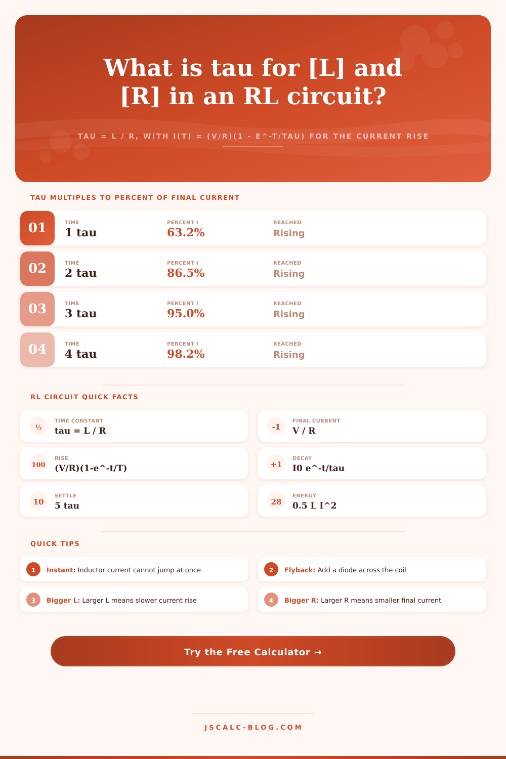
For example, if you hook up a 200 ohm coil to a 12 volt supply, the final current will be 60 milliamps, and the calculator figures out algebra for you so it can display that ceiling value. Better yet, it displays how far from that ceiling you’re getting at every instant because the inductor follows a particular curve as it rises and falls. Specifically, when time reaches one tau, the rising current is 63 percent of its final value; and once the voltage drops below that point, the falling current is only 37 percent of original value. No matter what the component values might be, those two numbers will always hold true.
For example, take a standard relay coil that’s rated at 200 ohms of resistance and 100 millihenries of inductance. That works out to a time constant of half a millisecond. One tau later, current has climbed to about 38 milliamps. This might feel slow but it feels fast in terms of mechanical hardware. Five tau later, at 2.5 milliseconds, the current is within one percent of intended target value of 60 milliamps, so engineers define that five tau value as the settle time since any difference beyond that is negligible.
The tool does that calculation immediately for you, then lets you check whether you have sufficient time from your switching frequency to get the coil energized before shutting it down again. That’s why inductor timing is important (current doesn’t turn off immediately); there are also very large voltage spikes created as the coil attempts to maintain flow. This can damages semiconductor switches, or even cause arcing across contacts. A flyback diode safely conducts this energy away and reduces it (about 5x time constants). Because we know how fast the current turns off when the drive stops (see the table of references above), we can determine whether the system has sufficient time to safely bleed down, keeping components cool and running reliabley. You should of checked if parts stays cool too.
You can also see these trade-offs instantly with preset scenario. A small buck converter inductor takes only microseconds to run its course, while a big filter choke take milliseconds. You can do this all without doing math by hand. Then there are the inputs: You can switch between units (e.g., henries vs. Microhenries), and they’ll convert them all behind the scenes, so that you just plug in your components’ numbers, and it figures out the rest.
And then you have your answer: When does the current arrive? It shows how much energy is in the magnetic field at every moment. That is what matters when you want to size a snubber or understand heat load. Whether it’s a power supply with switching spikes or a moddern mechanical relay you’re trying to time correctly, get the numbers right and you’ll protect your hardware from the kind of stress you can’t see.
The rise/decay pace will be set by the time constant; it establishes the rhythm of the circuit. That makes the delay predictable but also real. Learn the pace and you learn how to design systems that respond fast while not burning out their component.