RLC Resonant Frequency Calculator
Enter inductance L, capacitance C and resistance R to find the resonant frequency f0 = 1 / (2 pi sqrt of L C), the quality factor Q, the bandwidth BW = f0 / Q and the damping factor for a series or parallel RLC circuit, with every unit multiplier handled for you.
🎯Real Circuit Presets
🔌Circuit Inputs
Series and parallel use different Q formulas.
Series loss R, or the parallel load across the tank.
Coil inductance in microhenries, millihenries or henries.
Tuning capacitance in pico, nano or microfarads.
Compared against f0 to show detuning. Set 0 to skip.
Controls rounding on every result card.
🔢Formula Snapshot
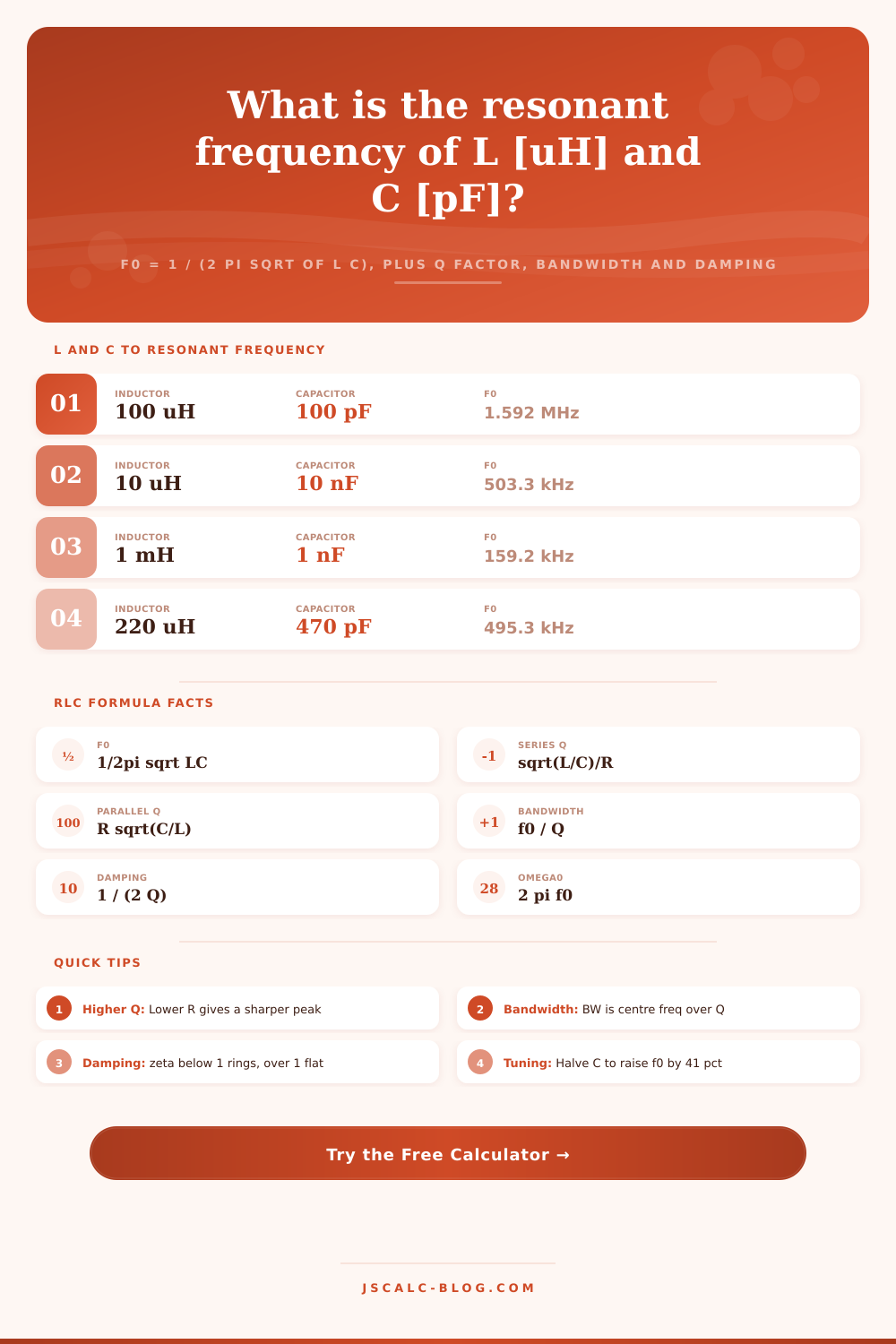
📋L and C to Resonant Frequency
| Inductance L | Capacitance C | Resonant f0 | Typical Use |
|---|---|---|---|
| 100 uH | 100 pF | 1.592 MHz | AM broadcast tank |
| 10 uH | 10 nF | 503.3 kHz | IF stage area |
| 1 mH | 1 nF | 159.2 kHz | LF signalling |
| 220 uH | 470 pF | 495.3 kHz | 455 kHz IF trim |
| 2.2 uH | 33 pF | 590.6 kHz | UHF match stub |
| 4.7 uH | 100 pF | 7.34 MHz | 40 m antenna trap |
| 100 mH | 100 nF | 1.592 kHz | Audio notch |
| 330 uH | 1 nF | 277.0 kHz | Switch mode ring |
📊Q Factor, Selectivity and Bandwidth
| Quality Factor Q | Selectivity | BW at 1 MHz | Damping zeta | Response |
|---|---|---|---|---|
| 1 | Very broad | 1 MHz | 0.5 | Underdamped |
| 2 | Broad | 500 kHz | 0.25 | Underdamped |
| 5 | Moderate | 200 kHz | 0.1 | Underdamped |
| 10 | Selective | 100 kHz | 0.05 | Underdamped |
| 50 | Sharp | 20 kHz | 0.01 | Underdamped |
| 100 | Very sharp | 10 kHz | 0.005 | Underdamped |
| 200 | Narrow peak | 5 kHz | 0.0025 | Underdamped |
| 0.5 | Critical | 2 MHz | 1.0 | Critical |
⚖Series vs Parallel RLC Summary
| Quantity | Series RLC | Parallel RLC | Note |
|---|---|---|---|
| Resonant f0 | 1 / 2pi sqrt LC | 1 / 2pi sqrt LC | Same for both |
| Quality Q | sqrt(L/C) / R | R sqrt(C/L) | R role flips |
| Bandwidth BW | f0 / Q | f0 / Q | Same relation |
| At resonance | Min impedance | Max impedance | R only vs high Z |
| Current | Peaks | Line current dips | Tank circulates |
| Low R effect | Raises Q | Lowers Q | Opposite trend |
| Typical role | Acceptor filter | Rejector tank | Pass vs block |
🗃Full L x C x R Comparison Grid
| L | C | R (ohm) | f0 | Series Q | BW |
|---|---|---|---|---|---|
| 100 uH | 100 pF | 10 | 1.592 MHz | 100 | 15.92 kHz |
| 100 uH | 100 pF | 50 | 1.592 MHz | 20 | 79.58 kHz |
| 220 uH | 470 pF | 8 | 495.3 kHz | 85.72 | 5.778 kHz |
| 1 mH | 1 nF | 20 | 159.2 kHz | 50.00 | 3.183 kHz |
| 10 uH | 10 nF | 2 | 503.3 kHz | 15.81 | 31.83 kHz |
| 4.7 uH | 100 pF | 5 | 7.34 MHz | 43.36 | 169.3 kHz |
| 2.2 uH | 33 pF | 3 | 590.6 kHz | 2.742 | 215.4 kHz |
| 330 uH | 1 nF | 15 | 277.0 kHz | 38.30 | 7.232 kHz |
| 100 mH | 100 nF | 100 | 1.592 kHz | 10.00 | 159.2 Hz |
| 68 uH | 220 pF | 6 | 1.301 MHz | 92.66 | 14.04 kHz |
⚙Formula Breakdown
💡Practical RLC Tuning Tips
RLC Resonant Frequency Calculator When you have an electric field in one component (a capacitor) swapping energy with a magnetic field in another component (coils), it cause resonance, peaking response at a certain frequency. Audio crossover networks and radio tuning dial rely on this same principle.
RLC Resonant Frequency Calculator turns passive components into four numbers: ring amount, width, sharpness of the peak, and center frequency. No need for solving differential equations on a napkin. Let tool handle the algebra while you concentrate on making sure your circuit works.
How to Use the RLC Calculator
Things get interesting where capacitive and inductive reactance cancel each other out; that’s the resonant frequency. It’s an equation that only depends on capacitance and inductance. No resistance are involved. Changing wire size won’t change center frequency. Combining 100 picofarads of capacitance with 100 microhenries of inductance will resonate around 1.592 megahertz. Regardless of what you add later to cause losses, this still hold. Everything else is based off that frequency.
Knowing the center isn’t enough; you’ve got to be able to determine thickness of its tip, or how fat top of the peak is. That’s when the Q factor enters into play. Q refers to selectivity. The lower the resistance of a series circuit, the higher the Q. You end up with a narrow spike with a tall peak. A parallel tank have the reverse effect. Increasing the parallel resistance increases the Q. Since they act as inverses, the calculator accounts for that difference in structure.
At resonant frequency, a series circuit acts like an open gate: it passes. A parallel tank blocks at the exact same pitch. Design a filter and get that wrong and you’re making something that does the exact opposite than what you designed.
Following on the heels of Q is bandwidth. This is amount of signal that passes through at a certain power level (half-power points). So if you have a Q of 100 and a resonant frequency of 1.5 megahertz then you have a bandwidth of just 15 kilohertz. That’s narrow enough to distinguish one AM station from another. Reduce your Q to say 10 and now you’ve got ten times as much bandwidth. More noise coming in but less selectivity too. A classic engineering tradeoff. Without extra stages you don’t usually gets both sharp rejection and a wide pass band.
And then, there’s damping. Damping describes how quickly it settle out after the signal goes away. Low damping (high Q) means ringing. The circuit will resonate at its natural frequency and then settles back down. Great if you’re trying to maintain a weak signal like a radio front end does. Terrible for a power supply snubber where ringing cause interference. When it’s over damped (damping factor greater than 1), it doesn’t ring or overshoot but settles slowly to zero. Because most tuned circuits require some energy storage, they resides in the underdamped region.
It has presets for some of the more popular applications such as a loudspeaker crossover or an AM radio tank circuit. How do those variables play out on real designs? Can I see that visualy? Yep. By tweaking the resistance, you’ll see the bandwidth narrow or stretch immediateley. Before building the hardware, it’s a good way to get a feel for how component values affect performance. If your capacitor selection puts the frequency in the ballpark, then great. It lets you visualize how these variables interact without building the hardware first. Does the resistor you chose result in excessive loss for what you’re doing? You can see that quicky too.
For those not familiar, you begin by selecting L and C to achieve your desired frequency. Afterward, you tweak R to determine how broad or selective you wish the response to be. For example, if you’re building a filter, you’ll choose high Q. If you’re suppressing oscillations in a switching circuit, then you’ll pick low Q. Either way, the math is identical, but the goal is completely differenter. It’s more important to understand why you need to tune for damping vs. Sharpness than it is to remember the equations. The equations spit out the values; it’s up to you to give them context based off what you’re trying to accomplish. When you realize just how much resistance tweaks bandwidth, everything else in the circuit starts to make sense.