LC Resonant Frequency Calculator
Find the resonant frequency of a pure LC tank with f0 = 1 divided by 2 pi times the square root of L times C, or rearrange to find the inductor or capacitor you need. Every run also reports the characteristic impedance Z0 = square root of L over C, the angular frequency, and the equal inductive and capacitive reactance at resonance.
📡Real LC Tank Presets
🔧Tank Inputs
Pick the unknown; the matching field below is ignored.
Controls rounding on every result card.
Coil inductance in the tank. Ignored when solving for L.
Tuning capacitance. Ignored when solving for C.
The frequency you want. Used only when solving for L or C.
🔢Formula Snapshot
📋Common L and C to Frequency
| Inductor L | Capacitor C | Frequency f0 | Typical Use |
|---|---|---|---|
| 220 uH | 470 pF | 495.6 kHz | AM IF region |
| 100 uH | 250 pF | 1.007 MHz | AM broadcast |
| 68 uH | 220 pF | 1.302 MHz | Longwave tune |
| 10 uH | 100 pF | 5.033 MHz | 60m ham band |
| 4.7 uH | 110 pF | 7.000 MHz | 40m ham band |
| 1.5 uH | 330 pF | 7.155 MHz | 40m Colpitts |
| 1 uH | 100 pF | 15.92 MHz | 20m region |
| 2.2 uH | 10 pF | 33.94 MHz | 10m band |
| 0.1 uH | 25 pF | 100.7 MHz | FM broadcast |
📻Frequency, Wavelength and Band
| Frequency f0 | Wavelength | Band Name | Note |
|---|---|---|---|
| 100 kHz | 3000 m | LF / VLF | Loop antennas |
| 1 MHz | 300 m | MF, AM | Medium wave |
| 3.5 MHz | 85.7 m | 80m HF | Ham lower HF |
| 7 MHz | 42.9 m | 40m HF | Shortwave |
| 10.7 MHz | 28.0 m | IF strip | FM receiver IF |
| 14 MHz | 21.4 m | 20m HF | DX favorite |
| 28 MHz | 10.7 m | 10m HF | Upper HF |
| 100 MHz | 3.00 m | VHF, FM | FM broadcast |
📏Unit Multipliers
| Unit | Quantity | In Base Unit | Note |
|---|---|---|---|
| 1 nH | Inductance | 1e-9 H | Nanohenry |
| 1 uH | Inductance | 1e-6 H | Microhenry |
| 1 mH | Inductance | 1e-3 H | Millihenry |
| 1 pF | Capacitance | 1e-12 F | Picofarad |
| 1 nF | Capacitance | 1e-9 F | Nanofarad |
| 1 uF | Capacitance | 1e-6 F | Microfarad |
🗃LC Tank Comparison Grid
| Inductor L | Capacitor C | Frequency f0 | Impedance Z0 | Omega w0 | Band |
|---|---|---|---|---|---|
| 330 uH | 1 nF | 277.0 kHz | 574 Ω | 1.74e6 rad/s | LF |
| 220 uH | 470 pF | 495.6 kHz | 684 Ω | 3.11e6 rad/s | AM IF |
| 100 uH | 100 pF | 1.592 MHz | 1000 Ω | 1.00e7 rad/s | MF, AM |
| 10 uH | 100 pF | 5.033 MHz | 316 Ω | 3.16e7 rad/s | 60m |
| 4.7 uH | 110 pF | 7.000 MHz | 207 Ω | 4.40e7 rad/s | 40m |
| 1 uH | 100 pF | 15.92 MHz | 100 Ω | 1.00e8 rad/s | 20m |
| 2.2 uH | 10 pF | 33.94 MHz | 469 Ω | 2.13e8 rad/s | 10m |
| 0.1 uH | 25 pF | 100.7 MHz | 63.2 Ω | 6.32e8 rad/s | FM VHF |
⚙Formula Breakdown
💡Practical Tuning Tips
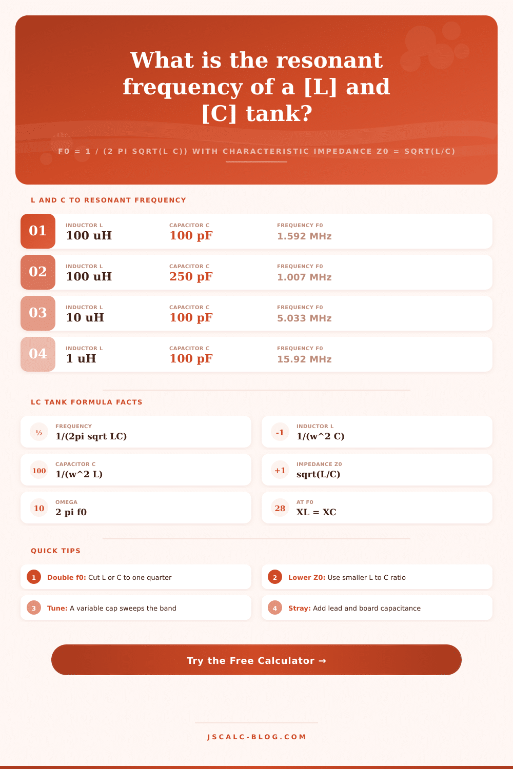
This LC resonant frequency calculator provide an immediate solution for a key formula used in filters and radio design. When you put a single capacitor and a single inductor together they form what’s known as a tank circuit that naturaly vibrates or oscillates at some frequency where energy goes back-and-forth between the electric field of the cap and the magnetic field of the inductor. That frequency is called the resonant frequency, expressed this way: The resonant frequency is calculated as f0 = 1 / (2 pi * sqrt(L*C)).
This calculator will solve this equation in all directions. Figure out the resonant frequency given a capacitor and an inductor you might be using; then reverse it to see exactly how much inductance or capacitance you need to achieve a desired frequency.
How to Use the Calculator
An inductor opposes a change in current by storing energy in a magnetic field. A capacitor opposes a change in voltage by storing energy in an electric field. When you connect them together, that stored energy can then oscillate back-and-forth between the components (much like a pendulum exchanges its speed for it’s height).
One particular frequency is “special.” The capacitive reactance become exactly the same size but opposite in sign as the inductive reactance. They cancel each other out. That’s called resonance. And that’s where this calculator comes into play. Because there’s no resistor in a pure LC tank, we only need to calculate its resonant frequency f0 and its characteristic impedance Z0. There are no bandwidths, quality factors, or damping terms here. Keeping the math nice and simple help keep the design intuition clear.
The heart of this tool is the simple formula: f0 = 1 / (2 pi * sqrt(L*C)). That one equation connects three variables. Any two known values give you the third. The “solve for” selector lets you select which quantity will be computed based off the other two. For example, set it to frequency; enter in your values for L and C, and it will calculate the resonant frequency f0. Change it to inductance, and it calculates what coil value result in the selected frequency with the given capacitor value. (That’s L = 1 / ((2 pi f0)^2 * C)) Set it to capacitance. It calculates the required capacitor value for a given inductor value at a desired frequency. The formula is C = 1 / ((2 pi f0)^2 * L). Rearranging these makes sense because real-world problems arise from all angles. Sometimes you’ve got some parts on the bench and want the frequency. Sometimes you know the frequency and need to pick out a part.
But then there’s the second part. “The second card shows how often this happens, but only half the story. It’s the other number: Z0 = sqrt(L/C). This is the level of impedance the tank has, and it’s what determines the impedance of the tank. “Unlike the frequency, it depends solely on the ratio between L and C, not on the product of L and C. So you could have two tanks with the same f0, but they might have wildly different levels of Z0, like one was built with a large coil and a small capacitor, and the other was built with a small coil and a large capacitor.”
It also reports the angular frequency omega0 = 2 pi f0 (in radians per second) and the reactance at resonance. At f0, the capacitive reactance XC and the inductive reactance XL will each be Z0. They will also be exactly equal to each other. Seeing all three numbers match is a handy sanity check that your entries make sense.
Think of a simple AM era tank with a 100 picofarad capacitor and a 100 microhenry coil. In base units, this becomes a 1e-10 farad capacitor (C) and a 1e-4 henry coil (L). Their product is 1e-14, whose square root is 1e-7. That’s about 1.592 megahertz, right smack in the middle of the medium wave band. The square root of 1e-4 over 1e-10 is 1e3, or 1000 ohms. So Z0 is 1000 ohms, and the reactance at resonance equals it. You never have to do all this arithmetic in your head again; all of the numbers comes up in the breakdown panel and the result cards.
Because real tanks have components that vary tremendously in size, the calculator accepts inductance in nanohenries, microhenries, millihenries, or henries. Capacitance is accepted in microfarads, nanofarads, or picofarads. Frequency may be input/read in either megahertz, kilohertz, or just plain old hertz. Internally, it converts everything to the SI base units, crunches the numbers, and automatically reformats all results back to a human friendly unit. In other words, you can type in a 4.7 uH coil next to a 110 pF capacitor without having to stop and count your zeroes. You get back a nice round number like 7.000 MHz, not some clunky series of exponents.
Instead of some abstract number, the preset buttons actualy load real circuits. A tank on the AM band comes up close enough to 1 MHz; a coil for the FM band is right at 100 MHz; a crystal ladder preset gets close to 10 MHz. There’s also room for a tuned loop antenna, a Colpitts oscillator, and that common FM receiver intermediate frequency strip at 10.7 MHz. Two other presets switch the tool into solve-for-C mode to size a cap for this tank, and solve-for-L mode to size a coil for this band. You can watch it tune a 7 MHz coil for the amateur bands or a 1 MHz tank for a different project. When you fill out the form, it calculates instantly and provides a working starting place, which you can tweak to taste.
LC design is fast. There are two rules of thumb. 1) Frequency is inversely proportional to the square root of the LC product; doubling the frequency means cutting that product to one quarter. Either cut each part in half or drop one to a quarter of its value. 2) The L-to-C ratio determines Z0 alone, independent of frequency. If you scale one part so that frequency remains the same, a lower L-to-C ratio will produce a lower Z0. You want a high-current low-impedance tank? Scale the other part up accordingly. These relationships allow you to trade a big physical coil for a big cap or vice versa. You can maintain the desired frequency at all times without losing anything. You’ll see how every change affects everything else immediatly on this calculator.
The formula can be used by students to see what happens when they change values of L and C, it’s neat the first time someone sees resonance happen. It allows hobbyists (I’ve built crystal radios, regenerative receivers, and simple oscillators) who choose components from tables of references to verify the operating band without having to solder anything up yet. For engineers designing RF filters and matching networks, being able to check Z0 and f0 at the same time is a big plus. This allows them to factor in the inevitable stray capacitance of leads and boards, which always pushes the actual frequency down. Whether you’re a beginner or an expert, putting in a coil and a cap and seeing four honest numbers come out is easier than trying to find a formula, then struggling with units conversions. In seconds, the LC resonant frequency calculator provides trusted results. It also tells you how it got there so you know why they’re trustworthy.