RC Low Pass Cutoff Frequency Calculator
Design a first-order RC low pass filter that passes low frequencies and attenuates high ones. Find the -3 dB cutoff with fc = 1 / (2 pi R C), solve for the resistor or capacitor you need, and check the attenuation in decibels at any test frequency along with the time constant and rolloff rate.
🎯Real RC Low Pass Presets
🔌Filter Inputs
Pick the unknown; enter the other values below.
Series resistor value in the chosen unit.
Multiplier applied to R.
Shunt capacitor to ground in the chosen unit.
Multiplier applied to C.
Desired -3 dB frequency when solving for R or C.
Multiplier applied to the target cutoff.
Frequency to evaluate the attenuation at.
Multiplier applied to the test frequency.
Controls rounding on every result card.
🔢Formula Snapshot
📊Frequency Ratio vs Attenuation
| f / fc Ratio | Gain |H| | Attenuation dB | Region |
|---|---|---|---|
| 0.1 | 0.995 | -0.04 dB | Passband |
| 0.5 | 0.894 | -0.97 dB | Passband |
| 1 | 0.707 | -3.01 dB | Cutoff fc |
| 2 | 0.447 | -6.99 dB | Stopband |
| 5 | 0.196 | -14.1 dB | Stopband |
| 10 | 0.0995 | -20.0 dB | 1 decade up |
| 20 | 0.0500 | -26.0 dB | Stopband |
| 100 | 0.0100 | -40.0 dB | 2 decades up |
🔌Common R and C to Cutoff fc
| Resistor R | Capacitor C | Cutoff fc | Time Constant tau |
|---|---|---|---|
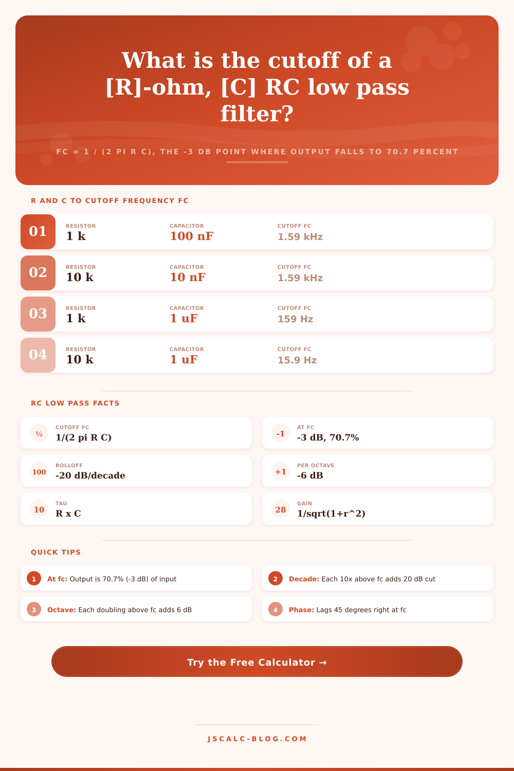
| 1 k | 100 nF | 1.592 kHz | 100 us |
| 10 k | 10 nF | 1.592 kHz | 100 us |
| 1 k | 1 uF | 159.2 Hz | 1 ms |
| 10 k | 1 uF | 15.92 Hz | 10 ms |
| 100 k | 1 nF | 1.592 kHz | 100 us |
| 1 k | 10 nF | 15.92 kHz | 10 us |
| 4.7 k | 10 nF | 3.386 kHz | 47 us |
| 2.2 k | 100 nF | 723.4 Hz | 220 us |
| 47 k | 1 nF | 3.386 kHz | 47 us |
| 330 | 470 nF | 1.026 kHz | 155 us |
📏Decibel and Octave Rolloff Guide
| Frequency Above fc | Change | Added Attenuation | Note |
|---|---|---|---|
| 1 octave (x2) | Double f | -6 dB | First-order slope |
| 1 decade (x10) | 10x f | -20 dB | First-order slope |
| 2 decades (x100) | 100x f | -40 dB | Deep stopband |
| 3 decades (x1000) | 1000x f | -60 dB | Very deep cut |
| Half power | At fc | -3.01 dB | Gain 0.707 |
| Half voltage | x1.732 fc | -6.02 dB | Gain 0.500 |
| Tenth voltage | x9.950 fc | -20.0 dB | Gain 0.100 |
🗃RC Low Pass Comparison Grid
| Resistor R | Capacitor C | Cutoff fc | Atten at 2x fc | Tau | Typical Use |
|---|---|---|---|---|---|
| 8 k | 1 nF | 19.89 kHz | -6.99 dB | 8 us | Audio anti-alias |
| 1.6 k | 100 nF | 994.7 Hz | -6.99 dB | 160 us | PWM smoothing |
| 16 k | 100 nF | 99.47 Hz | -6.99 dB | 1.6 ms | Sensor debounce |
| 160 k | 100 nF | 9.947 Hz | -6.99 dB | 16 ms | Supply noise |
| 160 | 1 nF | 994.7 kHz | -6.99 dB | 160 ns | RF roofing |
| 3.3 k | 1 nF | 48.23 kHz | -6.99 dB | 3.3 us | Op-amp input |
| 1 k | 10 nF | 15.92 kHz | -6.99 dB | 10 us | Audio band |
| 3.2 k | 10 nF | 4.974 kHz | -6.99 dB | 32 us | ADC input |
| 32 k | 100 nF | 49.74 Hz | -6.99 dB | 3.2 ms | Mains hum |
| 8 k | 10 nF | 1.989 kHz | -6.99 dB | 80 us | Sine shaper |
⚙Formula Breakdown
💡RC Low Pass Design Tips
In the analog world of electronics, we have a device called an RC low pass filter. It’s an electronic circuit that uses basic components: A capacitor and a resistor. You can find these easily. It doesn’t require fancy amplifiers or power supplies.
So why isn’t it good? Building this thing is the easy part. The hard part is finding the line where the right information gets through but noise stays out. That boundary is referred to as cutoff frequency, or fc. Make it too high and you risk letting unwanted frequencies pass; make it too low and you run the risk of losing your desired signal.
How to Use an RC Low Pass Filter
This equation is simple. Here’s how it reads. Fc = 1 / (2 pi R C). Simply plug in the resistance and capacitance values and you’ll get the frequency at which things start to change. Specifically, at that frequency, you’re seeing 70.7 percent of what you put in. That translates into a 3-dB drop in decibels, which is why they call this the -3 dB point. This is also referred to as the half-power frequency since voltage squared equals power.
A lot of folks think of the cutoff as a sharp border beyond which the sound simply ceases to exist. Not true. Although signal isn’t what it was before, there is still some left. And if you want your audio to be clear to 20kHz, then making the cutoff exactly on 20kHz are not the best option. What happens then is that you diminish the uppermost sounds that humans can hear. Make the cut-off higher instead, say at 30 or even 40kHz, and let it roll off at frequencies no one can hear.
When you’re down to two knowns it’s easy enough to do in your head. In real design, you often end up with three moving part. For example, you may want to block noise at a certain frequency but only have one of the capacitors on hand (so you’re down to the resistor). Or perhaps you want to use an analog-to-digital converter which has a specific cutoff. Enter the other two numbers and choose the one to solve for, and the calculator does all the algebra for you. The missing number pops out.
But there’s another nice feature here: you can plug in a test frequency and see what the attenuation will be. This is useful to make sure filter is doing what you want.
This simple circuit has one major drawback: it’s a soft slope of loss. After the cut-off frequency, higher frequencies drops at the rate of 20 dB per decade. This means that for each doubling of frequency, you lose 6 dB. For every ten times increase in frequency, you lose 20 dB. That’s not steep enough to filter out high-frequency radio interference entirely. Consider connecting a couple (or even three) RC stages in series. Each extra stage add an extra 20 dB per decade slope.
Knowing the tradeoff matters more then knowing the formula. The other thing to be aware of is what’s called the time constant, or tau: tau = R x C. That tells you how fast the circuit respond to abrupt voltage changes. A high-value (big) capacitor and resistor produce a long time constant (slow response) at a low cutoff frequency. That can make for a strong filter, but it may strip out too much information if you’re filtering a sensor’s digital pulse. It may eliminate the real signal completly.
Tau is listed alongside frequency results by the tool. It reminds us that time-domain behavior and frequency response are linked ideas. When designing these filters you don’t do exact math but you do set boundaries. The goal is to leave the signal clean without introducing delay in the time domain.
Begin by using a canned filter (i.e. Start with a canned filter, such as anti-aliasing or PWM smoothing, and then tune the parts to the desired noise characteristics. Examine the decibel drop at the noise source’s frequency. If that is not enough, reduce the cutoff frequency or add another stage. Doing so would of got you off the ground without problems caused by noisy circuits down the road.