Reflection Coefficient Calculator
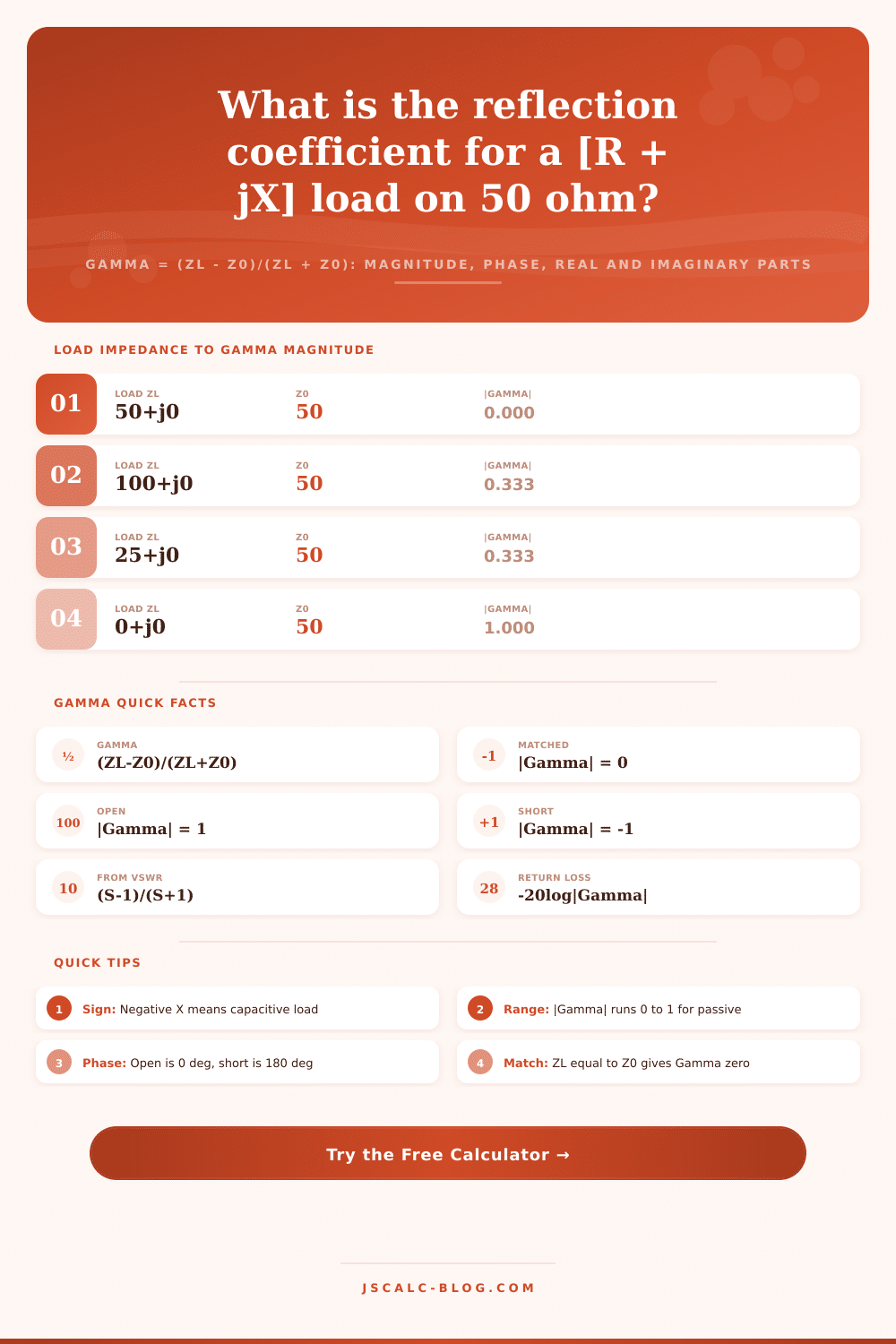
Compute the complex reflection coefficient Gamma from a load impedance ZL = R + jX on a real system impedance Z0, or from a measured VSWR. The tool returns the magnitude |Gamma|, the phase angle in degrees, and the separate real and imaginary parts using Gamma = (ZL - Z0) / (ZL + Z0).
📡Choose a Mode
🎯Real Load and Line Presets
📝Impedance and Line Inputs
Characteristic impedance of the line, usually 50 or 75 ohm.
Real part of the load impedance ZL = R + jX.
Imaginary part. Positive is inductive, negative is capacitive.
Voltage standing wave ratio, 1 or greater. Gives magnitude only.
Controls rounding on every result card and row.
Unit used for the phase angle result card.
🔢Formula Snapshot
📋Purely Resistive Load Examples
| Load ZL (ohm) | Z0 (ohm) | Gamma (real) | |Gamma| | Phase |
|---|---|---|---|---|
| 50 + j0 | 50 | 0.000 | 0.000 | 0° |
| 0 + j0 (short) | 50 | -1.000 | 1.000 | 180° |
| Open circuit | 50 | 1.000 | 1.000 | 0° |
| 100 + j0 | 50 | 0.333 | 0.333 | 0° |
| 25 + j0 | 50 | -0.333 | 0.333 | 180° |
| 150 + j0 | 50 | 0.500 | 0.500 | 0° |
| 75 + j0 | 50 | 0.200 | 0.200 | 0° |
| 16.7 + j0 | 50 | -0.500 | 0.500 | 180° |
📊VSWR to Magnitude and Return Loss
| VSWR (S : 1) | |Gamma| | Return Loss | Power Reflected | Match Quality |
|---|---|---|---|---|
| 1.00 : 1 | 0.000 | Infinite dB | 0.0% | Perfect |
| 1.10 : 1 | 0.048 | 26.4 dB | 0.2% | Excellent |
| 1.20 : 1 | 0.091 | 20.8 dB | 0.8% | Very good |
| 1.50 : 1 | 0.200 | 14.0 dB | 4.0% | Good |
| 2.00 : 1 | 0.333 | 9.5 dB | 11.1% | Fair |
| 3.00 : 1 | 0.500 | 6.0 dB | 25.0% | Poor |
| 5.00 : 1 | 0.667 | 3.5 dB | 44.4% | Bad |
| 10.0 : 1 | 0.818 | 1.7 dB | 66.9% | Severe |
📏Common System Impedances
| Z0 (ohm) | Typical Use | Cable Family | Note |
|---|---|---|---|
| 50 | RF and test gear | RG-58, RG-8, LMR | Best power handling balance |
| 75 | Video and cable TV | RG-6, RG-59 | Lowest loss for signals |
| 93 | Legacy data links | RG-62 | Low capacitance per foot |
| 100 | Ethernet twisted pair | Cat5e, Cat6 | Differential balanced pair |
| 120 | Industrial data bus | CAN, RS-485 | Termination resistor value |
| 300 | Legacy TV antenna | Twin-lead ribbon | Folded dipole feed |
| 377 | Free space | None | Impedance of a vacuum |
🗃Complex Load Reflection Comparison Grid
| Load ZL (ohm) | Z0 (ohm) | Gamma Real | Gamma Imag | |Gamma| | Phase (deg) | VSWR |
|---|---|---|---|---|---|---|
| 50 + j0 | 50 | 0.000 | 0.000 | 0.000 | 0.0 | 1.00 |
| 100 + j0 | 50 | 0.333 | 0.000 | 0.333 | 0.0 | 2.00 |
| 25 + j0 | 50 | -0.333 | 0.000 | 0.333 | 180.0 | 2.00 |
| 50 + j50 | 50 | 0.200 | 0.400 | 0.447 | 63.4 | 2.62 |
| 50 - j50 | 50 | 0.200 | -0.400 | 0.447 | -63.4 | 2.62 |
| 75 + j25 | 50 | 0.243 | 0.146 | 0.283 | 31.0 | 1.79 |
| 30 - j40 | 50 | 0.040 | -0.518 | 0.520 | -85.6 | 3.16 |
| 100 + j50 | 50 | 0.385 | 0.231 | 0.449 | 31.0 | 2.63 |
| 0 + j0 | 50 | -1.000 | 0.000 | 1.000 | 180.0 | Infinite |
| 73 + j42.5 | 50 | 0.264 | 0.229 | 0.350 | 40.9 | 2.08 |
⚙Formula Breakdown
💡Practical Matching Tips
So you’ve got your coax hooked up, your antenna’s tuned, fired up the transmitter, and noticed that the reflected power increases as the power meter needle dip. If you’re transmitting RF energy from a transmitter to an antenna without some of it being lost in standing waves, you aren’t alone. What happened at that connection point is explained by the reflection coefficient. It will tell you why it bounced back, how much, and what part of the signal was reflected.
A lot of folks gets stuck on VSWR, which is a scalar ratio. However, Gamma, the reflection coefficient, are complex with both real and imaginary parts and magnitude and phase. That tells you if your problem is reactance or resistance. Knowing the difference means the difference between actualy designing to match and blindly guessing.
What Is the Reflection Coefficient?
That said, when a signal reach a load ZL on a transmission line with characteristic impedance Z0, it doesn’t stop there. Part goes into the load and part are reflected back towards the source. Gamma is ratio of the reflected voltage to the incident voltage. When ZL equals Z0 (perfect match), then Gamma equals zero and there is no return whatsoever.
At the other extreme, if it’s an open or a short circuit, then Gamma equals one, which is a complete reflection. Between those two extremes, it’s a partial reflection and knowing the phase angle will tell you exactly where the voltage peaks and nulls is located along the cable. A lot of folks only look at their high VSWR and don’t consider how the phase angle makes the impedance look inductive or capacitive at transmitter end. The look entirely changes with cable length.
In reality, no antenna is simply a resistor. If you’re exactly on resonance, then a half-wave dipole may indeed be 73 ohms resistive, but there’s going to be some reactance as well. Hence Gamma is complex. The real part of Gamma represent the resistance mismatch, and the imaginary part corresponds to the reactance. Negative reactance are capacitive, positive reactance is inductive.
So when you compute Gamma, you’re really getting a map in two dimensions that describes just how much off balance your load is. Once you plug in your resistance and reactance, the calculator does all the math for you, avoiding any wrestling with complex division by hand. It returns four separate cards. Magnitude, phase, real part and imaginary part.
Why these? This tells you which component to add. If you have a large imaginary part, then it wants an inductor or tuning capacitor rather than another transformer. This is simple math, but boring if done by hand. It’s (ZL. Z0)/(ZL + Z0). Since we’re working with complex numbers, you can expand that into real and imaginary parts by multiplying the numerator and denominator by conjugate of the denominator. Then just take the square root of the sum of the squares of each. That gives you the magnitude.
The phase is the arctan of the imaginary over the real. That angle is crucial for transmission line transforms or when trying to match a circuit at the end of piece of coax cable. A negative phase means a capacitive load. It is below resonance. Inductance is what you want to add to pull it toward the center. Positive phase? There is too much inductance. Add some capacitance. Knowing the imaginary portion is positive or negative will save you from adding the wrong kind of thing and increasing the VSWR rather then decreasing it.
But you don’t always have a vector analyzer or even a VSWR meter. Then you won’t be able to get the imaginary part of the load or its phase either. All you’ll get from just a VSWR reading is the magnitude of Gamma. This is the ratio of the voltage coming into your antenna to what goes down your transmission line. That’s (VSWR (1)/(VSWR + 1)), giving you the return loss. It is amount of power going back at you.
The percentage of reflected power it gives you is vital for knowing if you will burn out your amp. If your VSWR is 2 to 1, that represents an 11 percent reflection. Sounds like not much. But it adds up over time, heats up your feedline and other things. But now you’re still flying blind as to how to correct it because you don’t know the specific type of load causing the problem. You know there is one, but you don’t know what type.
For example, engineers will run a preset like this one: a 50 plus j50 ohm load (perfectly resistive) to examine the effect of only pure reactance on the reflection coefficient. It increases magnitude to 0.447 which equals a VSWR of 2.62. This happens all because of that +j50 reactance. Adding a series capacitor cancels it out and brings the reflection back down toward zero.
So we see, then, that impedance matching isn’t just making a low VSWR. It’s canceling out errors in BOTH reactance AND resistance at once. It is not just the former or latter. You want your Gamma to land right on origin of the Smith Chart. These numbers are used by RF engineers, antenna builders, and ham radio operators for troubleshooting signal paths. They help avoid expensive trial and error when you’re trying to design a matching network or verify that a cable has been terminated correctly.
To begin with, look at whether your mismatch is primarily reactive or resistive. Next, look at the phase angle. It will tell you which components to choose next based off the phase angle. If it’s negative, you have a capacitive load that needs to be corrected with inductance. Positive means the load is inductive so it requires correction using capacitance. Now that you know what each of those four result cards mean, you stop guessing and start tuning.
Reflection coefficient isn’t just a formula but also a map that tells you precisely where your energy is going wrong and how to bring it back on track. You should of seen this coming sooner.