Pulley Belt Length Calculator
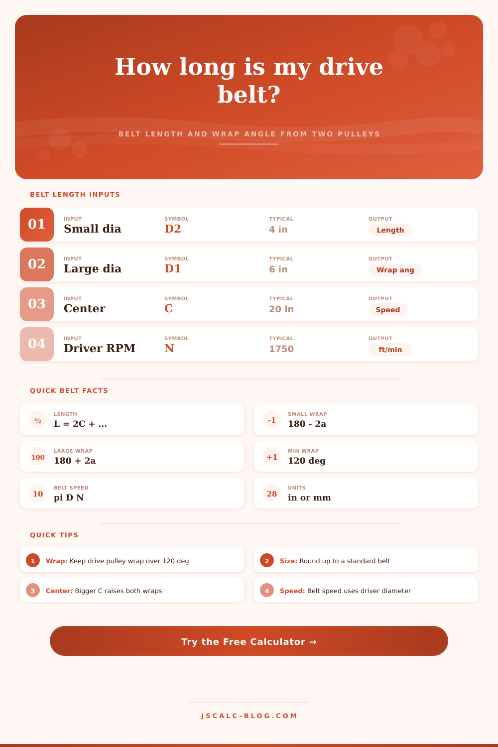
Find the open-belt length, small and large pulley wrap angles, and belt speed for a two-pulley drive from the two pulley diameters and the center distance, in inches or millimeters.
🎯Real Drive Presets
📝Pulley Inputs
Pitch diameter of the larger sheave.
Pitch diameter of the smaller sheave.
Shaft-to-shaft spacing. Used in belt-length mode.
Used only when solving for center distance.
Speed of the driving pulley. Set 0 to skip belt speed.
🔢Formula Symbols
⚙Full Formula Breakdown
📏Belt Length vs Center Distance
| Center C (in) | D1 = 6 in | D2 = 4 in | Belt Length (in) | Small Wrap |
|---|---|---|---|---|
| 8 | 6 | 4 | 31.83 | 165.6° |
| 12 | 6 | 4 | 39.79 | 170.4° |
| 16 | 6 | 4 | 47.77 | 172.8° |
| 20 | 6 | 4 | 55.76 | 174.3° |
| 24 | 6 | 4 | 63.75 | 175.2° |
| 30 | 6 | 4 | 75.74 | 176.2° |
| 36 | 6 | 4 | 87.74 | 176.8° |
🗂Drive Comparison Grid
| Drive | D1 (in) | D2 (in) | Center (in) | Belt Length (in) | Small Wrap |
|---|---|---|---|---|---|
| Motor to spindle 3:1 | 9 | 3 | 16 | 51.41 | 158.4° |
| Equal 5in pulleys | 5 | 5 | 15 | 45.71 | 180.0° |
| Alternator drive | 5.5 | 2.5 | 9 | 30.82 | 160.8° |
| Lathe countershaft | 7 | 3.5 | 18 | 52.66 | 168.8° |
| Table saw arbor | 4 | 3 | 12 | 35.02 | 175.2° |
| Wide ratio 10in/2in | 10 | 2 | 22 | 63.58 | 159.0° |
| Compressor belt | 12 | 3 | 18 | 60.69 | 151.0° |
| Drill press step | 4.5 | 2 | 10 | 30.37 | 165.6° |
📊Wrap Angle vs Diameter Ratio
| D1 ∕ D2 | (D1−D2)∕(2C) | Small Wrap θ1 | Large Wrap θ2 | Notes |
|---|---|---|---|---|
| 1.0 (equal) | 0.00 | 180.0° | 180.0° | Even grip both |
| 1.5 | 0.05 | 174.3° | 185.7° | Very safe |
| 2.0 | 0.10 | 168.5° | 191.5° | Good grip |
| 3.0 | 0.15 | 162.7° | 197.3° | Watch tension |
| 4.0 | 0.25 | 151.0° | 209.0° | Add center C |
| 5.0 | 0.33 | 141.5° | 218.5° | Near limit |
| 6.0 | 0.42 | 130.3° | 229.7° | Consider idler |
📐Standard V-Belt Lengths & Unit Conversions
| V-Belt | Nominal (in) | Pitch Length (in) | Millimetres (mm) | Section |
|---|---|---|---|---|
| A31 | 33.0 | 32.3 | 820 | A / 4L |
| A45 | 47.0 | 46.3 | 1176 | A / 4L |
| A55 | 57.0 | 56.3 | 1430 | A / 4L |
| B48 | 51.0 | 49.8 | 1265 | B / 5L |
| B60 | 63.0 | 61.8 | 1570 | B / 5L |
| 1 in | 1.00 | – | 25.4 | Conversion |
| 1 ft | 12.00 | – | 304.8 | Conversion |
💡Practical Belt Tips
You have a motor spinning at nearly 2,000 rpm and a pump that barely needs half that speed to move water effectivly. Putting one behind the other doesn’t require simply placing a rubber strip between two wheel and calling it good enough. Once someone wants to make a new belt drive from scratch or fix an old one, the belt’s geometry becomes complex. It calls for specific answers regarding belt length, tension, and how much of the belt actualy grips each pulley.
Everyone guesses at the former because they wrap some string around their drawing and pray they match one of the stock sizes found on hardware store shelf. Use the calculator above to do all that math for you based off your approximate measures. You won’t have to guess anymore, and you can get down to building.
Why Belt Geometry Matters
So what is this belt length business all about? First of all, it isn’t just a simple matter of adding the straight line from one shaft to the other and then adding some curvature to it to fit over wheels. It’s made up of two straight parts and two curved parts (arcs) whose lengths depends solely upon the way the belt contacts the pulleys. In particular, if you have a driver and driven pulley of unequal diameter, the belt doesn’t approach either one parallel to its centerline. Instead there will be some entry angle. And that angle alters the apparent wrap on either side. The bigger pulley sees increased contact area; the smaller sees less.
Why is that important? No friction holds this drive system together except where the belt is in contact with sheave. Fewer points of contact mean fewer points of grip and more opportunity for slip under load. How do you know? These are the wrap angles. With a perfect set-up where both pulleys is the same size (same diameter), each receives one-hundred eighty degrees of contact. That’s the baseline.
Most drivetrains incorporate a size difference between pulleys in order to obtain their desired speed ratio. When this size difference grow larger, so does the decrease in wrap angle for the smaller pulley. A common mechanical design rule is to keep the smaller pulley wrap angle at no less than one hundred twenty degrees. Below this number, you’re putting too much pressure on the friction coefficient alone. During heavy load shifts and/or startups (when torque typically spikes), the belt slip. If your math show an alarmingly low wrap, you must use an idler pulley to increase contact and tension.
The second parameter that matters big-time is center distance. The farther apart the shafts are from each other, the wider the wrap angle will be on both pulleys (more secure drive, but longer belt). It also impact flexibility. If the center distance is super-short, then the belt has to make a tight corner around the little pulley with every pass through that area. This causes excess heating due to hysteresis, and wears down the belt at an accelerated rate. Somewhere in-between is a sweet spot for the center distance where the belt stay taut.
And this is where the tool shines: You can put in your known belt length as a fixed inventory item, then use it to solve for center distance. Just plug in the part number and discover what shaft spacing fits the bill.
As important as geometry are speed parameters. Power transmission depends on how fast the belt spins. Centrifugal force will lift a V-belt off the pulley if it spin too quickly. This leads to less contact and slipping of the drive system. Run it too slowly, and it requires too wide a belt to transmit equal power. The calculator determines this velocity number using the driver’s rotation speed and its diameter. This is a quick way to check your work before committing to a design.
Maybe the ratio you’d like to achieve will cause the belt to spin in a speed range where common rubber compounds will wear out too soon. The tool’s reference table shows how all of those variables work together in various situations. For example: Pulleys of equal diameter give max stability but no speed change; a wider diameter ratio gives steeper angle and less wrap; etc.
The V-belt table is also a good reminder that real world stock rarely matches your theoretically desired length. You’ll almost always be rounding up to the next size you can get. And then a tensioner (or adjustable motor mount) takes care of that little discrepancy. Spending time trying to design a perfect fit in the spreadsheet only leads to frustration in the shop when you can’t find that specific part number.
In the end, a belt drive is a balance of strength, speed, and space. You are relying on friction to keep it all together, gaining some rotational advantage in exchange for more physical distance. If you get the initial geometry correct, then you’ll save yourself from noisy operation or premature failure and, even worse, broken equipment down the line. Instead of relying on intuition, let the numbers be your guide and go with what the geometry tells you. When selecting your pulleys and measuring your shafts, let those measurements rule your hand instead of just your gut feeling. That difference between a successful long-term drive and a short-lived failure can often depend on whether you got the length right and respected the wrap angle at the outset.