Pipe Diameter and Flow Rate Calculator
Solve the continuity equation Q = A × v for flow rate, pipe diameter, or velocity. Enter any two values and get the third, plus cross-section area, in imperial or metric units.
🚰Real Pipe Presets
📝Continuity Inputs
The unknown field is disabled and filled from Q = A × v.
Use the true inside bore, not the nominal pipe size.
Sets the recommended velocity band shown below.
Reminder only – enter the real inside diameter above.
🔢Continuity Snapshot
💧Recommended Velocities by Service
| Service | Typical Range (ft/s) | Metric (m/s) | Notes |
|---|---|---|---|
| Pump suction (water) | 2 – 4 | 0.6 – 1.2 | Low speed limits cavitation |
| Pump discharge (water) | 4 – 10 | 1.2 – 3.0 | General service header |
| Building supply line | 4 – 8 | 1.2 – 2.4 | Limits noise and hammer |
| Gravity drain / sewer | 2 – 8 | 0.6 – 2.4 | Keep above 2 ft/s to scour |
| Compressed air main | 15 – 30 | 4.5 – 9.0 | Higher gas velocity is normal |
| Low pressure steam | 65 – 130 | 20 – 40 | Sized by mass flow of steam |
| Viscous oil line | 1 – 3 | 0.3 – 0.9 | Slow flow cuts friction loss |
📏Pipe Size vs Flow at 5 ft/s
| Nominal Size | Sch 40 Bore (in) | Area (sq in) | Flow at 5 ft/s (GPM) | Flow (L/min) |
|---|---|---|---|---|
| 1/2 in | 0.622 | 0.304 | 4.7 | 17.9 |
| 3/4 in | 0.824 | 0.533 | 8.3 | 31.4 |
| 1 in | 1.049 | 0.864 | 13.5 | 51.0 |
| 1-1/2 in | 1.610 | 2.036 | 31.7 | 120.1 |
| 2 in | 2.067 | 3.356 | 52.3 | 197.9 |
| 3 in | 3.068 | 7.393 | 115.2 | 436.1 |
| 4 in | 4.026 | 12.730 | 198.4 | 751.0 |
| 6 in | 6.065 | 28.890 | 450.2 | 1704.2 |
🗂Diameter vs Area and Flow (Comparison)
| Inside Dia (in) | Area (sq in) | Q at 3 ft/s (GPM) | Q at 5 ft/s (GPM) | Q at 8 ft/s (GPM) |
|---|---|---|---|---|
| 0.50 | 0.196 | 1.8 | 3.1 | 4.9 |
| 0.75 | 0.442 | 4.1 | 6.9 | 11.0 |
| 1.00 | 0.785 | 7.3 | 12.2 | 19.6 |
| 1.50 | 1.767 | 16.5 | 27.5 | 44.0 |
| 2.00 | 3.142 | 29.4 | 48.9 | 78.3 |
| 3.00 | 7.069 | 66.1 | 110.1 | 176.2 |
| 4.00 | 12.566 | 117.5 | 195.8 | 313.3 |
| 6.00 | 28.274 | 264.4 | 440.6 | 705.0 |
🔄Flow Unit Conversions
| From | GPM | L/min | m³/h | ft³/s |
|---|---|---|---|---|
| 1 GPM (US) | 1 | 3.785 | 0.2271 | 0.002228 |
| 1 L/min | 0.2642 | 1 | 0.06 | 0.000589 |
| 1 m³/h | 4.403 | 16.667 | 1 | 0.009810 |
| 1 ft³/s | 448.8 | 1699.0 | 101.94 | 1 |
⚙Full Formula Breakdown
📋Nominal Pipe Areas Reference
| Nominal Size | Sch 40 Bore (in) | Bore (mm) | Area (sq in) | Area (mm²) |
|---|---|---|---|---|
| 1/2 in | 0.622 | 15.8 | 0.304 | 196 |
| 3/4 in | 0.824 | 20.9 | 0.533 | 344 |
| 1 in | 1.049 | 26.6 | 0.864 | 558 |
| 2 in | 2.067 | 52.5 | 3.356 | 2165 |
| 3 in | 3.068 | 77.9 | 7.393 | 4770 |
| 4 in | 4.026 | 102.3 | 12.730 | 8213 |
| 6 in | 6.065 | 154.1 | 28.890 | 18639 |
💡Practical Sizing Tips
When you turn on your garden hose and turn the handle all the way, the water starts to spray out as mist: Why? This happens because there isn’t enough room for all of that water volume to pass through. Annoying, yes. But this is typicaly not a problem with your water supply. The problem is that the pipe size doesn’t match the amount of fluid trying to pass through it.
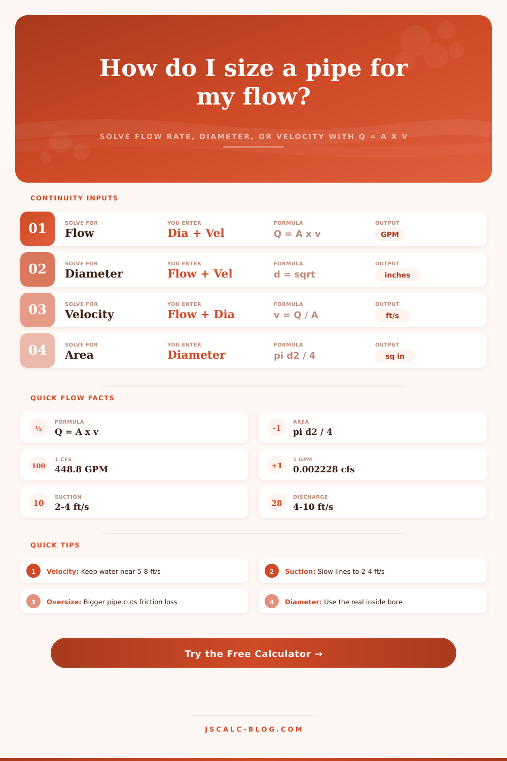
And that’s where the continuity equation come in, relating pipe area, flow rate, and velocity. It requires no college degree in fluid dynamics to apply, but it does require knowing what variables represents in the real-world. So how does this apply? It’s as simple as this: Flow = Velocity x Cross-Sectional Area.
How to Choose the Right Pipe Size
That means that to double your flow (assuming you are keeping velocity constant) without changing anything else you would of needed to double size of pipe. Similarly, if you restrict the output of same volume of water by forcing it into a smaller area, you will have to increase the velocity. Most people misinterpret this and assume that larger pipes just carries more water. Not true. Larger pipes enable you to push that water at a slower pace.
And slow is good in nearly every system. Velocity sounds great, until you have to listen to it Turbulence causes banging pipe and eroded fittings. Moving water at a rate of ten feet per second or higher generates enough turbulence to be bad news. The calculator on top solve for whatever unknown variable you want it to solve for. But actualy determining which target velocity makes sense for your application requires you to do the heavy lifting.
For your pump discharge line, it’s common wisdom to keep the water velocity between 4 and 10 ft/sec. That strikes the right balance between energy cost and pipe size. You don’t need big pipes if you’re just going slow. Any faster, you start wasting energy fighting friction, and you risk damaging your infrastructure.
Suction lines are a whole other story. In this case you don’t want high velocities (two to four feet per second is about all). Why? You want to avoid what’s called cavitation. What’s that? When the suction line inlet pressure gets too low, small amounts of vapor bubble up into the liquid and then violently implode. This sounds like gravel rattling in the casing, and it tears apart impeller rapidly. By keeping the water flowing slowly you will also have higher pressure on the intake side, protecting the most expensive part of your system.
There is also friction loss. Frictional head loss roughly goes up as the square of velocity. That means if you double your velocity you quadruple the frictional loss and thus energy needed to push it down the line. A slight increase in diameter (even just a nominal pipe size) can provide huge savings during the life of the system by oversizing a long run. A bit more PVC or copper now saves much less than running an electric pump all day every day to fight steep friction losses pushing water uphill.
The table on the page makes this clear; small increases in diameter result in dramatic jumps in flow capacity because area is scaled by the square of the radius. We also see people commonly referring to what they believe is size of their pipes, when it is actualy the inside diameter. For example, a Schedule 40 steel two inch pipe is not two inches in diameter. There is space taken up by the walls. If you’re off on this number (diameter), you’re off on the area and everything else downstream from there. Always reference the actual internal diameter of your pipe size/schedule/material combination. Small detail, big deal.
But the end result is that your pipe size is a balance between money and effort: how much does it cost to buy materials versus how much will it cost in the long run, in terms of maintenance and energy used to pump? That’s what the tool makes easy: it crunches the numbers for you (translating units and calculating area), freeing you up to use your engineering judgment. Instead of an abstract formula, it gives you real-world dimensions.
The next time you’re working on plumbing, and you hear a pipe rattling or see a loss of pressure, consider velocity. Odds are that the fluid is moving too fast for the space it has. Opening up the pathway is typically the solution: slow things down. The water’s trying to go somewhere, let it. Give it room to do so, and it will do it not only efficiently but also quiet. Respect the space within the wall, and you get that consistent arc coming out the end of the hose nozzle.