Single Resistor Voltage Drop Calculator
Work out the voltage dropped across one series resistor with V = I × R, the power it burns with P = I² × R, the voltage left at the load, and the standard wattage rating to pick after derating.
🔌Real Resistor Presets
📝Resistor Inputs
IR mode uses current and resistance. Dropper mode sizes a resistor from a supply rail down to a load voltage.
IR mode uses this only to report the leftover load voltage.
Dropper mode: the voltage you want remaining after the resistor.
🔢Formula Snapshot
⚡Standard Resistor Wattage Ratings
| Rating | Watts | Typical Body | Common Use |
|---|---|---|---|
| 1/8 W | 0.125 W | Tiny axial / SMD 0805 | Signal, pull-ups, low current |
| 1/4 W | 0.25 W | Standard axial | LED series, general hobby use |
| 1/2 W | 0.5 W | Larger axial | Moderate current droppers |
| 1 W | 1.0 W | Chunky axial / MELF | Higher current series drops |
| 2 W | 2.0 W | Metal oxide film | Rail droppers, snubbers |
| 5 W | 5.0 W | Ceramic wirewound | Power droppers, bleeders |
| 10 W | 10.0 W | Aluminium clad | High power, needs heatsink |
📏E12 Standard Resistor Values
| Base Value | ×10 | ×100 | ×1k | ×10k |
|---|---|---|---|---|
| 1.0 Ω | 10 Ω | 100 Ω | 1.0 kΩ | 10 kΩ |
| 1.2 Ω | 12 Ω | 120 Ω | 1.2 kΩ | 12 kΩ |
| 1.5 Ω | 15 Ω | 150 Ω | 1.5 kΩ | 15 kΩ |
| 1.8 Ω | 18 Ω | 180 Ω | 1.8 kΩ | 18 kΩ |
| 2.2 Ω | 22 Ω | 220 Ω | 2.2 kΩ | 22 kΩ |
| 2.7 Ω | 27 Ω | 270 Ω | 2.7 kΩ | 27 kΩ |
| 3.3 Ω | 33 Ω | 330 Ω | 3.3 kΩ | 33 kΩ |
| 3.9 Ω | 39 Ω | 390 Ω | 3.9 kΩ | 39 kΩ |
| 4.7 Ω | 47 Ω | 470 Ω | 4.7 kΩ | 47 kΩ |
| 5.6 Ω | 56 Ω | 560 Ω | 5.6 kΩ | 56 kΩ |
| 6.8 Ω | 68 Ω | 680 Ω | 6.8 kΩ | 68 kΩ |
| 8.2 Ω | 82 Ω | 820 Ω | 8.2 kΩ | 82 kΩ |
🗂Current vs Resistance Comparison Grid
| Current | Resistance | V Drop | Power | 2× Power | Watt Pick |
|---|---|---|---|---|---|
| 1 mA | 10 kΩ | 10 V | 0.010 W | 0.020 W | 1/8 W |
| 5 mA | 1 kΩ | 5 V | 0.025 W | 0.050 W | 1/8 W |
| 10 mA | 1 kΩ | 10 V | 0.100 W | 0.200 W | 1/4 W |
| 20 mA | 330 Ω | 6.6 V | 0.132 W | 0.264 W | 1/2 W |
| 50 mA | 100 Ω | 5 V | 0.250 W | 0.500 W | 1/2 W |
| 100 mA | 70 Ω | 7 V | 0.700 W | 1.400 W | 2 W |
| 250 mA | 10 Ω | 2.5 V | 0.625 W | 1.250 W | 2 W |
| 500 mA | 10 Ω | 5 V | 2.500 W | 5.000 W | 5 W |
| 1 A | 4.7 Ω | 4.7 V | 4.700 W | 9.400 W | 10 W |
| 2 A | 1 Ω | 2 V | 4.000 W | 8.000 W | 10 W |
🌡Power Derating Guide
| Calculated Power | 1.5× Margin | 2× Margin | 3× Margin | Notes |
|---|---|---|---|---|
| Up to 0.08 W | 1/8 W | 1/4 W | 1/4 W | Signal level, runs cool |
| 0.08 to 0.16 W | 1/4 W | 1/2 W | 1/2 W | Typical LED dropper |
| 0.16 to 0.33 W | 1/2 W | 1 W | 1 W | Warm to the touch |
| 0.33 to 0.66 W | 1 W | 2 W | 2 W | Give it some air |
| 0.66 to 1.6 W | 2 W | 5 W | 5 W | Ceramic wirewound |
| 1.6 to 3.3 W | 5 W | 10 W | 10 W+ | Needs open mounting |
| Above 3.3 W | 10 W+ | Heatsink | Heatsink | Aluminium clad on metal |
⚙Full Formula Breakdown
📋Drop and Power Examples
| Scenario | Setup | V Drop | Power | Rating |
|---|---|---|---|---|
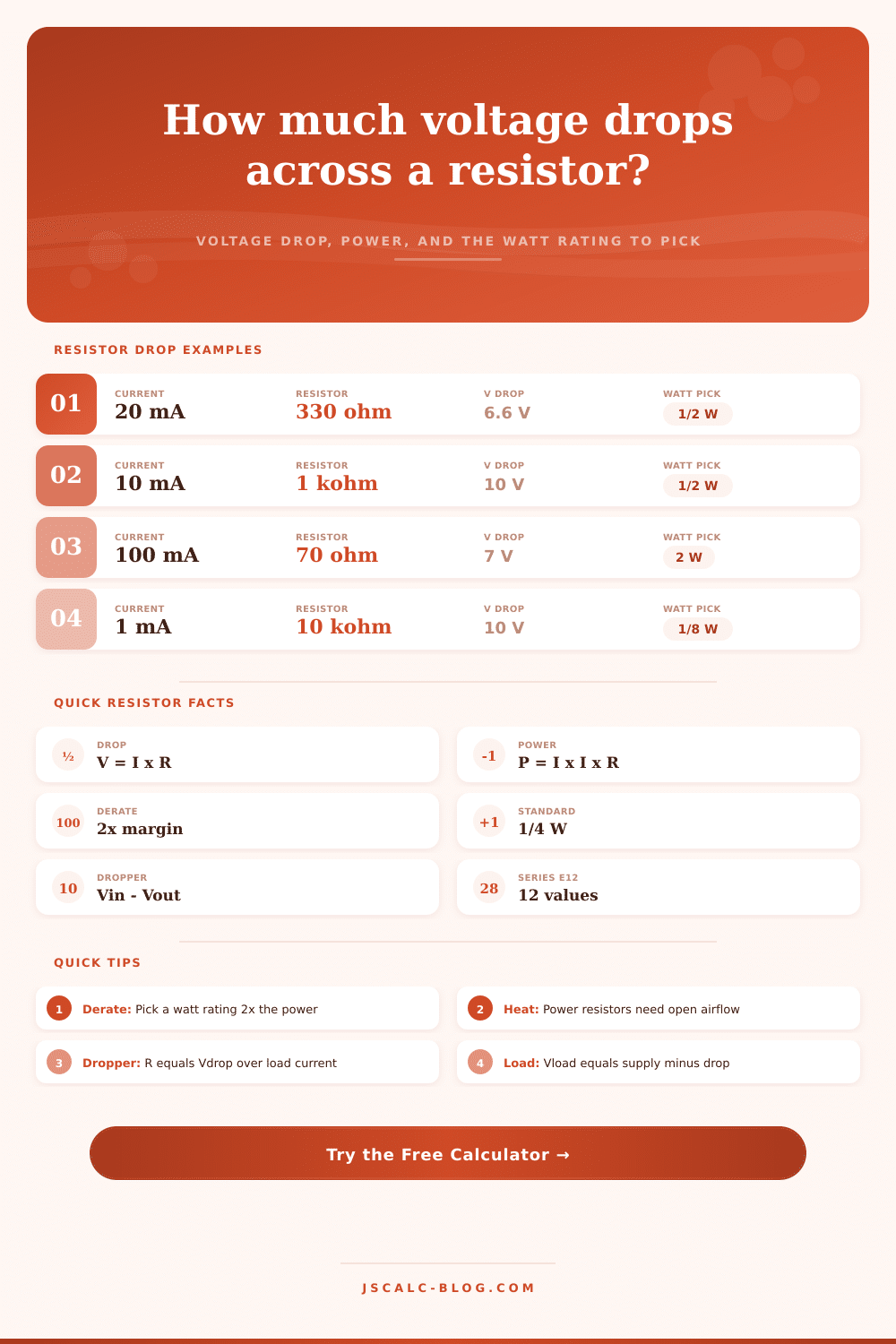
| LED series resistor | 20 mA, 330 Ω | 6.6 V | 0.132 W | 1/2 W |
| 12 V to 5 V dropper | 0.1 A, ΔV 7 V | 7.0 V | 0.700 W | 2 W |
| Pull-up resistor | 0.33 mA, 10 kΩ | 3.3 V | 0.001 W | 1/8 W |
| Current sense shunt | 1 A, 0.1 Ω | 0.1 V | 0.100 W | 1/4 W |
| Series 1k limiter | 10 mA, 1 kΩ | 10.0 V | 0.100 W | 1/4 W |
| Power dump resistor | 0.5 A, 20 Ω | 10.0 V | 5.000 W | 10 W |
| 3.3 V rail dropper | 60 mA, ΔV 1.7 V | 1.7 V | 0.102 W | 1/2 W |
| HV bleeder | 2 mA, 100 kΩ | 200 V | 0.400 W | 2 W |
💡Practical Resistor Tips
You stare at a flickering LED and wonder why your circuit behaves like it has a mind of its own. A few resistor sits in there, dropping a certain amount of voltage, and they’re doing things different than you’d expect. Why? Since their voltage drop are related to the amount of charge pushing past them, knowing that relationship will keep your components from silently failing or melting.
Ohm’s law is the underlying rule here: the voltage drop over a resistor is equal to the current flowing through it multiplied by resistance. It seems easy enough in theory; just remember that when this happen, power gets created (as in watts), and that thermal energy doesn’t simply evaporate into nothingness. That means your components could be heating up without you realizing it, until they melt.
Why Resistors Get Hot
Enter your resistance and current in series into the calculator above, and it’ll do the math for you, showing you exactly how many watt are being wasted versus those powering your circuit. Knowing this value in advance is key; every single resistor has a maximum power rating beyond which it’ll fail.
Quarter-watt resistors is included just about anywhere you can find an electronics kit being sold, which means most hobbyist begin there. They’re more than sufficient for low-current applications such as microcontroller inputs and other pull-up resistors, where current flow are small. But put a three-hundred-ohm resistor in series with something that draws twenty milliamps and you’re dissipating a tenth of a watt. It may not sound like much, but if that’s enough to push a standard quarter-watt resistor up to half its capacity, you’ll have an uncomfortably warm component on your hands.
Within the limits of a sealed enclosure or even in a breadboard, heat build up fast and doesn’t give much warning. That’s why derating is important. You shouldn’ should select a resistor rated exactly for your calculated power load, but rather something twice as high to give yourself some breathing room. A resistor pushed to the max age more quickly and shifts in value. So if you calculate that you require half a watt of resistive capacity, you selects a one-watt component which will operate cool enough to be touched on an hour of continuous use. It is a minor additional cost, but it provides far better peace of mind by ensuring consistent circuit behavior over time.
But there’s another thing: A series resistor is eating up part of your supply voltage, leaving less for what follows it in the chain. Say you’re dropping a dozen volts to five volts for a sensor. That leaves seven volts. And where does that seven-volt difference have to go? It goes through the resistor as heat. So unless the last component is pulling a big current (which may not be the case), you’ve got significant power dissipation going on here. You need to trade off good voltage control with efficiency hit of wasting power like this.
Before you even glance at printed code or color bands, you can get an idea for how much abuse a resistor can take by looking at its physical dimensions. For example, a small surface-mount device can’t dissipate nearly as much heat as a big old axial lead component. That component has a lot of exposed ceramic body for the air to blow on. Airflow is more important than most people think, and packing high-power resistors into a tight space without any ventilation makes those components ticking time bombs ready to overheat and fail. Either give your high-power components some breathing room or fasten them to metal (which will serve as a heat sink).
Part of this hobby is having to settle for something that’s close but not a perfect match based off what you have available in terms of resistance value from your standard E12 series selections. Round up to the next closest stock number and live with it. It doesn’t need to be mathematically perfect, it only needs to work as intended under actualy operating conditions.
In summary, the art of circuit construction is all about weighing those energy costs, since each voltage lost to a resistor is work performed against the current of electricity. This means wasted heat, something you want to account for as well as selecting components that can comfortabley stand up to the heat load. Respect the physics of resistance, and your batteries will last longer and your LEDs will shine brighter.