Pneumatic Cylinder Force Calculator
Size an air cylinder in seconds. Enter the bore and rod diameter, your shop air pressure, and the action, and this tool returns extend push force and retract pull force in pounds and newtons, the effective piston areas, and the SCFM of free air the cylinder draws while it cycles.
🎯Real Air Cylinder Presets
📏Cylinder and Air Inputs
Inside diameter of the cylinder tube, the full piston.
Applies to both bore and rod diameter fields.
Piston rod diameter, subtracted on the pull stroke.
Regulated gauge pressure at the cylinder port.
1 bar equals 14.5038 psi of gauge pressure.
Chooses which force headlines the summary card.
Travel per stroke, used for air volume per cycle.
Full extend plus retract cycles each minute for SCFM.
Seal and friction losses. Typical range 85 to 95%.
Controls decimals shown on the result cards.
🔢Formula Snapshot
📋NFPA Bore Size, Area and Push Force at 90 psi
| Bore Diameter | Piston Area | Push Force at 90 psi | Force in Newtons |
|---|---|---|---|
| 0.75 in | 0.442 in2 | 40 lbf | 177 N |
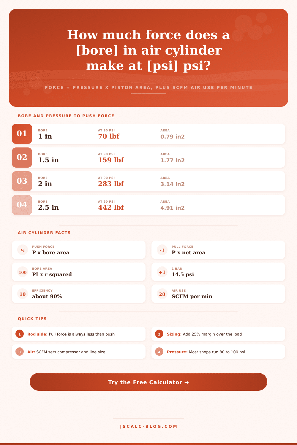
| 1 in | 0.785 in2 | 71 lbf | 314 N |
| 1.5 in | 1.767 in2 | 159 lbf | 707 N |
| 2 in | 3.142 in2 | 283 lbf | 1258 N |
| 2.5 in | 4.909 in2 | 442 lbf | 1965 N |
| 3.25 in | 8.296 in2 | 747 lbf | 3321 N |
| 4 in | 12.566 in2 | 1131 lbf | 5031 N |
| 5 in | 19.635 in2 | 1767 lbf | 7861 N |
| 6 in | 28.274 in2 | 2545 lbf | 11319 N |
| 8 in | 50.265 in2 | 4524 lbf | 20122 N |
📏psi and bar Pressure Conversion
| Gauge psi | Gauge bar | kPa | Common Use |
|---|---|---|---|
| 30 psi | 2.07 bar | 207 kPa | Light air tools |
| 60 psi | 4.14 bar | 414 kPa | Small actuators |
| 80 psi | 5.52 bar | 552 kPa | General shop line |
| 90 psi | 6.21 bar | 621 kPa | Standard rating |
| 100 psi | 6.89 bar | 689 kPa | Presses and clamps |
| 120 psi | 8.27 bar | 827 kPa | Max shop pressure |
| 145 psi | 10.0 bar | 1000 kPa | High-force limit |
⇆Extend Versus Retract for a 2 in Bore
| Rod Diameter | Bore Area | Net Rod-Side Area | Push at 90 psi | Pull at 90 psi |
|---|---|---|---|---|
| 0.375 in | 3.142 in2 | 3.031 in2 | 283 lbf | 273 lbf |
| 0.500 in | 3.142 in2 | 2.945 in2 | 283 lbf | 265 lbf |
| 0.625 in | 3.142 in2 | 2.834 in2 | 283 lbf | 255 lbf |
| 0.750 in | 3.142 in2 | 2.700 in2 | 283 lbf | 243 lbf |
| 1.000 in | 3.142 in2 | 2.356 in2 | 283 lbf | 212 lbf |
| 1.375 in | 3.142 in2 | 1.657 in2 | 283 lbf | 149 lbf |
🏭Typical Operating Pressures by Application
| Application | Typical Pressure | Common Bore | Why |
|---|---|---|---|
| Part clamping | 80 to 90 psi | 1 to 2 in | Firm hold, no marking |
| Gate and diverter | 60 to 80 psi | 1.5 to 3 in | Fast, light load |
| Conveyor stop | 40 to 60 psi | 0.75 to 1.25 in | Cushion the impact |
| Press and stamp | 90 to 120 psi | 4 to 8 in | Max force needed |
| Lifting station | 90 to 100 psi | 2.5 to 4 in | Steady vertical load |
| Part ejector | 60 to 90 psi | 0.75 to 1.5 in | Quick short stroke |
🗃Bore Size Force Comparison Grid
| Bore Size | Piston Area | Force at 60 psi | Force at 90 psi | Force at 120 psi | Typical Use |
|---|---|---|---|---|---|
| 0.75 in | 0.442 in2 | 27 lbf | 40 lbf | 53 lbf | Small ejector |
| 1 in | 0.785 in2 | 47 lbf | 71 lbf | 94 lbf | Part feeder |
| 1.5 in | 1.767 in2 | 106 lbf | 159 lbf | 212 lbf | Light clamp |
| 2 in | 3.142 in2 | 188 lbf | 283 lbf | 377 lbf | Work clamp |
| 2.5 in | 4.909 in2 | 295 lbf | 442 lbf | 589 lbf | Lift station |
| 3.25 in | 8.296 in2 | 498 lbf | 747 lbf | 996 lbf | Gate actuator |
| 4 in | 12.566 in2 | 754 lbf | 1131 lbf | 1508 lbf | Heavy push |
| 5 in | 19.635 in2 | 1178 lbf | 1767 lbf | 2356 lbf | Stamping ram |
| 6 in | 28.274 in2 | 1696 lbf | 2545 lbf | 3393 lbf | Large press |
| 8 in | 50.265 in2 | 3016 lbf | 4524 lbf | 6032 lbf | Forming press |
⚙Formula Breakdown
💡Air Cylinder Sizing Tips
The problem isn’t moving the load. I’m sure the machine will do that. No, the issue is moving it consistentley as pressure fluctuates and seals gets gunked up. You’ve got a job to do, and you need to choose an air cylinder to do it. The answer’s at your fingertips on the page. Not only does it do the arithmetic, it lets you concentrate on physics.
All it has to do is start with simple equation that governs all things pneumatic… Force = Pressure x Area. It is a neat statement in theory. A place where many folks makes sizing errors in practice because they don’t remember that what’s called “area” are not simply the bore size you read about in the catalog. That’s why the tool first requests your bore diameter; that’s what defines how much piston face will be exposed to air pressure. For example, with a two-inch bore, there’s approximately three square inches of piston face exposed. At 90 psi, that’s a theoretical thrust of two hundred and eighty pounds.
How to Choose the Right Air Cylinder
In a perfect world, that’s the ideal number but the next parameter matter more. To understand why, you must enter rod diameter because the piston rod takes up space on the retracting side of the cylinder. So the effective area used to push the rod out is always larger than the area used to pull the rod back in. And if your machine has to lift weight on the return stroke, that diminished pull force are critical. Fortunately, the calculator automaticly recognizes that geometric reality and does not require you to subtract the area of circles in your head.
No real machines is frictionless. Some power will be lost to seal drag and guide bushings before it even reach the load. This is why we use an efficiency slider. Ninety percent is for a well-lubricated standard cylinder, while eighty-five percent accounts for older units or applications where heavy side loads might be present. It keeps you grounded in reality rather than textbook ideals. You don’t care about what comes out of the compressor, you just want to know what really gets to tool face.
Builders often neglect the other half of the equation: consumption. They only notice it when their header pressure collapse and their compressor screams for more air. Based off cycle rate and stroke length, the calculator finds SCFM. As each cylinder fires, there’s a volume of air being displaced by the piston every cycle. That volume has to be compressed. Run a bunch of them fast and they will all want to consume more than you can deliver from your little air receiver. This happens before the next kick from the compressor. Save yourself from having to buy a larger compressor or install oversized piping after the fact if you know your free air delivery requirement up front.
Mixing imperial shop air with metric components can be a headache, but not here; it deals with converting pressure and bore sizes without breaking a sweat. Six bar of pressure translates into psi for final force calculation whereas an eighty-millimeter bore becomes inches inside. Regardless of whether you type in pounds or newtons, you’ll get back results in both. That means no classic mistake of mixed units entered by hand on a spreadsheet, which is how projects gets put on hold while awaiting clarifying email messages.
Don’t select a cylinder so small as to just barely provide enough force on paper. Go with a 25% margin above expected force, allowing for the natural wear over time and also for pressure drops in long runs of airlines. The preset buttons will allow you to run typical set-ups fast, such as a heavy press ram or a clamping station. You’ll see how swapping one variable change both air usage and force output. That’s the gist of mechanical sympathy, and it’s simple.
Don’t waste energy by oversizing a cylinder and draining your compressor dry. Apply the data. Verify that you have enough airflow to support the cycle and enough muscle for it to do the job. Once you get a handle on how bore area, supply pressure and cycle rate relate to each other, you’re no longer guessing and can begin to design confidentally.