Heatsink Thermal Resistance Calculator
Size a heatsink by solving for the required sink-to-ambient thermal resistance. Enter the power to dissipate, the maximum junction temperature, the ambient temperature, plus the junction-to-case and case-to-sink resistances, and the tool returns the theta-sa your heatsink must beat, the total allowable theta-ja, the resulting junction temperature for a candidate sink, and the thermal margin.
🔥Real Heatsink Sizing Presets
📝Heatsink Design Inputs
Steady-state heat the device sheds into the sink.
Datasheet absolute max, or a derated target.
Air temperature around the heatsink at worst case.
Internal resistance from the die to the package tab.
Interface material: grease, pad, or mica plus screw.
A specific heatsink you are checking, for Tj and margin.
Subtracts a margin from Tj_max before sizing.
Controls rounding on every result card.
🔢Formula Snapshot
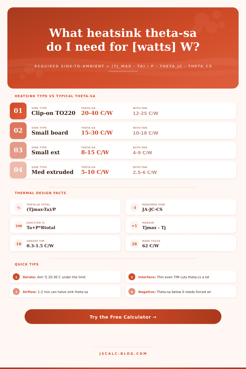
📈Heatsink Type vs Typical Theta-SA
| Heatsink Type | Size Class | Natural Air | Light Fan | Strong Fan |
|---|---|---|---|---|
| Clip-on TO-220 fin | Tiny | 20-40 C/W | 15-25 C/W | 12-18 C/W |
| Small PCB heatsink | Small | 15-30 C/W | 10-18 C/W | 8-14 C/W |
| Small extruded block | Small | 8-15 C/W | 5-9 C/W | 4-7 C/W |
| Medium extruded | Medium | 5-10 C/W | 3-6 C/W | 2.5-4 C/W |
| Large finned plate | Large | 2-5 C/W | 1.5-3 C/W | 1-2 C/W |
| Big pin-fin array | Large | 1.5-4 C/W | 1-2 C/W | 0.8-1.5 C/W |
| CPU tower cooler | Extra large | 0.3-1 C/W | 0.2-0.5 C/W | 0.1-0.4 C/W |
| Liquid cold plate | Active | 0.1-0.5 C/W | 0.08-0.3 C/W | 0.05-0.2 C/W |
🧩Interface Material Theta-CS Guide
| Interface (TIM) | TO-220 theta-cs | TO-247 theta-cs | Note |
|---|---|---|---|
| Dry metal to metal | 1.2-2.0 C/W | 0.8-1.4 C/W | Air gaps, avoid |
| Thermal grease | 0.3-0.5 C/W | 0.2-0.4 C/W | Thin even film |
| Silicone pad | 0.6-1.0 C/W | 0.4-0.8 C/W | Clean, no wipe |
| Mica plus grease | 0.8-1.4 C/W | 0.6-1.0 C/W | Adds isolation |
| Graphite sheet | 0.4-0.7 C/W | 0.3-0.5 C/W | Reusable, dry |
| Phase-change pad | 0.3-0.6 C/W | 0.2-0.5 C/W | Melts on heat |
| Ceramic insulator | 0.5-0.9 C/W | 0.4-0.7 C/W | High voltage |
📊Typical Package Theta-JC Values
| Package | Theta-JC | Bare Theta-JA | Example Device |
|---|---|---|---|
| TO-220 | 1.0-3.0 C/W | 60-75 C/W | Regulator, MOSFET |
| TO-247 | 0.4-1.0 C/W | 40-55 C/W | Power IGBT, SiC |
| TO-263 D2PAK | 1.0-2.0 C/W | 50-65 C/W | SMD power FET |
| DPAK TO-252 | 2.0-5.0 C/W | 90-110 C/W | Small SMD FET |
| TO-3P | 0.6-1.2 C/W | 35-50 C/W | Audio output |
| Power module | 0.1-0.5 C/W | n/a | IGBT half-bridge |
| LED star MCPCB | 2.5-8 C/W | n/a | 3W power LED |
🗃Worked Sizing Comparison Grid
| Power P | Tj_max | Ambient | Theta-JC+CS | Allow Theta-JA | Required Theta-SA |
|---|---|---|---|---|---|
| 5 W | 125 C | 40 C | 2.0 C/W | 17.0 C/W | 15.0 C/W |
| 10 W | 125 C | 40 C | 2.0 C/W | 8.5 C/W | 6.5 C/W |
| 15 W | 150 C | 50 C | 2.0 C/W | 6.7 C/W | 4.7 C/W |
| 25 W | 150 C | 45 C | 1.5 C/W | 4.2 C/W | 2.7 C/W |
| 40 W | 150 C | 50 C | 1.5 C/W | 2.5 C/W | 1.0 C/W |
| 65 W | 100 C | 40 C | 0.8 C/W | 0.92 C/W | 0.12 C/W |
| 100 W | 150 C | 45 C | 0.6 C/W | 1.05 C/W | 0.45 C/W |
| 150 W | 150 C | 50 C | 0.5 C/W | 0.67 C/W | 0.17 C/W |
| 3 W | 105 C | 40 C | 4.0 C/W | 21.7 C/W | 17.7 C/W |
| 8 W | 110 C | 55 C | 2.0 C/W | 6.9 C/W | 4.9 C/W |
⚙Formula Breakdown
💡Practical Heatsink Tips
Thermal design is a bit of a guessing game, but reversing the thinking can make heatsink size more understandable. Usually engineer choose a prebuilt heatsink and ask whether it’s good enough to prevent the chip melting. With this calculator, you describe the conditions (how much heat it can lose and at what temperatures) and it asks how well a heatsink should resist that heat. Specify your parameters, and it spits out precisely what level of heat resistance you need. It makes a vague “feels hot” into a measurable spec for searching through catalog.
The silicon die loses heat via several resistances, expressed in degrees Celsius per watt. Theta-jc is the resistance due to die size and package manufacturing. Theta-cs is the resistance due to whatever thermal interface material you use (pad, grease, mica). Lastly, theta-sa are the resistance due to your heatsink dumping heat into the surrounding air. Since these are in series, each adds directly.
How to Choose the Right Heatsink
If we know the max temperature allowed for our silicon, and the current room temperature, the difference between those two numbers is the total allowable rise from ambient to junction…which is just the total watts being dissipated, divided by that difference. That’s the total thermal budget. It’s a tool that solves for the one thing you CAN change: The sink-to-ambient resistance. It deducts the interface and internal resistances from your total and tells you how much theta-sa your heatsink can absorbs. So if it says six degrees per watt, anything below that will work.
Anything with an extruded aluminum profile in still air is usually going to be somewhere between five and ten degrees per watt, which means you already know at a glance whether there’s a chance of a passive solution working. There’s no reason to model fin efficiency or even try to simulate airflow to get a rough answer.
The required resistance comes out as zero or a negative sometimes from the math. This is not a bug in the tool, and it is also not a sign that your numbers are wrong. Physics is telling you that all of your temperature budget has been used up by other internal resistances. A part might be rated for 65 watts and need to be kept cool in hot ambient air. There may be nothing left over for the heatsink to do anything about. No amount of passive fin area are going to save you. You will need forced air cooling to reduce the effective resistance, a derating strategy at higher powers, or a package with lower internal resistance.
You want to check that candidate sink will work just as much as you want to determine its size. Plug in your desired thermal resistance for a particular part you’ve found, and it’ll predict the resulting junction temperature. Then it’ll show you the margin: how many degrees below the limit are you? If you’re above zero, it’s got some headroom; if you’re below zero, you won’t survive higher ambient temperatures or dusty conditions. Having that predicted temperature on the screen alongside the datasheet limit turns a number from an abstract resistance value into a clear yes or no decision.
Most folks overlook the interface material. It matters more then you might think. Dry metal-to-metal contact on a TO-220 package increases the temperature by two degrees per watt of resistance. That’s an additional thirty degrees of junction rise at fifteen watts for no good reason. Applying a thin, even layer of thermal grease reduces this resistance considerabley, often saving twenty degrees or more in junction rise. This typically buys you more temperature headroom than moving up to a slightly larger heatsink. Choosing the proper interface material is a small detail which make a HUGE difference when it comes to real-world reliability.
There are presets for typical situations like this one, ranging from large load resistors for high-power IGBT modules down to small regulators. These pre-populate realistic numbers on page so you can see what sort of resistance you need based off the amount of power being dissipated. It’s a good rule of thumb to always specify a component with a junction temperature significantly cooler than the rated max, say, 20-30 degrees cooler. This creates some margin, or “guard band,” to account for variations in the thermal resistance of individual components, and also protects against aging due to long exposure at elevated temperatures.
You work within your constraints, and the tool calculates your target. Then you validate that your selection has enough margin above the limit so that everything checks out. Not only will things survive, but there should of been plenty of time for the heat to spread out without struggling against the physical laws of the package itself.