Linear Regulator Efficiency Calculator
Estimate the efficiency of an LDO or linear regulator from input voltage, output voltage, load current, and quiescent current. See the percentage of power delivered, the watts wasted as heat, the dropout headroom, and how a linear part compares to a switching regulator.
🎯Real Regulator Presets
🔋Regulator Inputs
Unregulated supply feeding the regulator input pin.
Regulated rail delivered to your load.
Current drawn by the circuit on the output rail.
Applies to the load and quiescent current fields.
Regulator's own draw to ground, from its datasheet.
Optional. Typical buck converter is 85 to 95 percent.
Minimum Vin minus Vout the part needs to regulate.
Controls rounding on the result cards.
🔢Formula Snapshot
📊Vin to Vout Efficiency Ceiling
| Input Vin | Output Vout | Efficiency Cap | Wasted Fraction |
|---|---|---|---|
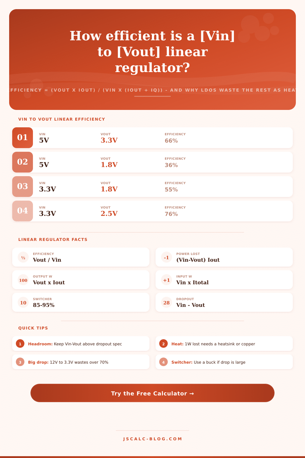
| 5 V | 3.3 V | 66% | 34% as heat |
| 5 V | 2.5 V | 50% | 50% as heat |
| 5 V | 1.8 V | 36% | 64% as heat |
| 3.3 V | 2.5 V | 76% | 24% as heat |
| 3.3 V | 1.8 V | 55% | 45% as heat |
| 3.3 V | 1.2 V | 36% | 64% as heat |
| 9 V | 3.3 V | 37% | 63% as heat |
| 12 V | 5 V | 42% | 58% as heat |
| 12 V | 3.3 V | 27% | 73% as heat |
| 24 V | 5 V | 21% | 79% as heat |
🔥Power Lost at Common Loads
| Vin - Vout | At 100 mA | At 250 mA | At 500 mA | At 1 A |
|---|---|---|---|---|
| 0.5 V | 0.05 W | 0.13 W | 0.25 W | 0.50 W |
| 1.0 V | 0.10 W | 0.25 W | 0.50 W | 1.00 W |
| 1.7 V | 0.17 W | 0.43 W | 0.85 W | 1.70 W |
| 2.2 V | 0.22 W | 0.55 W | 1.10 W | 2.20 W |
| 3.7 V | 0.37 W | 0.93 W | 1.85 W | 3.70 W |
| 5.7 V | 0.57 W | 1.43 W | 2.85 W | 5.70 W |
| 7.0 V | 0.70 W | 1.75 W | 3.50 W | 7.00 W |
| 8.7 V | 0.87 W | 2.18 W | 4.35 W | 8.70 W |
⚖Linear vs Switching Regulator
| Scenario | Vin | Vout | Linear Eff | Switcher Eff | Better Choice |
|---|---|---|---|---|---|
| Small drop | 3.3 V | 3.0 V | 91% | 88% | Linear (LDO) |
| Battery rail | 4.2 V | 3.3 V | 79% | 92% | Either |
| USB to core | 5 V | 3.3 V | 66% | 90% | Depends on load |
| USB to low | 5 V | 1.8 V | 36% | 90% | Switcher (buck) |
| 9V to logic | 9 V | 3.3 V | 37% | 90% | Switcher (buck) |
| 12V to 5V | 12 V | 5 V | 42% | 91% | Switcher (buck) |
| 12V to logic | 12 V | 3.3 V | 27% | 90% | Switcher (buck) |
| Car to 5V | 14.4 V | 5 V | 35% | 91% | Switcher (buck) |
| 24V rail | 24 V | 5 V | 21% | 90% | Switcher (buck) |
📡Popular Linear Regulator Parts
| Part | Type | Dropout | Quiescent | Typical Use |
|---|---|---|---|---|
| LM7805 | Standard | 2.0 V | 5 mA | 12V to 5V legacy |
| LM317 | Adjustable | 2.0 V | 3.5 mA | Bench and general |
| AMS1117-3.3 | LDO | 1.1 V | 5 mA | 5V to 3.3V boards |
| LD1117 | LDO | 1.1 V | 5 mA | Logic rails |
| MCP1700 | Low Iq LDO | 0.18 V | 1.6 uA | Battery sensors |
| TLV70033 | Nano LDO | 0.27 V | 31 uA | Coin cell 3.3V |
| AP2112-3.3 | LDO | 0.25 V | 55 uA | Modern 3.3V |
⚙Formula Breakdown
💡Design and Thermal Tips
One basic way to drop voltage is with a linear regulator, which offers advantage of being simple, but at cost of inefficiency. How much is wasted as heat? And how much makes it through to your load? Plug in your variables: load current, input voltage, output voltage, and regulator quiescent current. The tool then calculates useful power, total draw, efficiency percentage, watts lost, and the amount of dropout headroom left on your supply. Whether that’s enough to justify a low-dropout regulator in your design, or whether you need something more complicated, this will help you determine the answer.
Linear regulators is similar to a variable resistor from the input to the output. To maintain a constant output voltage, they drops excess voltage inside the regulator on an internal transistor. The current from your load flows through that internal transistor. Each volt it drops is heat. That’s what linear efficiency means. Rather than recycling the voltage change it turns it into heat right there. How well it do this depends on how much voltage you have in vs. Out. That means an LDO can be both good and bad depending on the design.
How Linear Regulators Work and Lose Heat
The formula is Output Power / Input Power. Simply put: Vout * Iout / (Vin * (Iout + Iq)). If quiescent current is much less than load current then we simplify the formula. So Vout / Vin is roughly the efficiency. The max efficiency of any linear regulator are limited by this ratio. A linear regulator can’t be more efficient than 66% even with the best part if it’s supplying 3.3 volts from 5 volts. This knowledge limits which parts is right for a specific use.
Four vital numbers is displayed on the results panel. The efficiency card includes the percentage of input power that reached the load. Below it, the maximum voltage ratio are noted. The lost power card shows the wattage dissipated within the regulator (i.e., input power (output power)). This is roughly equal to the load current x voltage drop + a tiny quiescent term. Output v Input card reflects useful watts compared to total draw. It makes wastefulness clear as day. Dropout headroom card reflects Vin -Vout and alerts you when the margin is dangerously thin different than your spec.
Let’s use an example where you pull out a 5 volt USB rail to generate 3.3 volts via an AMS1117 to drive a microcontroller that draws 500 milliamps. It also consumes 5 milliamps of quiescent current. That means the output power is 1.65 watts, and it consumes approximately 2.53 watts from the input. So it’s losing roughly 0.85 watts as heat. That’s enough to make a small surface mount package warm, so copper layout does matter. If you increase the input voltage to 12 volts for a comparable 3.3 volt rail, then efficiency plummets to around 27 percent and the heat generated increases to over four watts. This tells us we might want to rethink what we’re doing here.
Linear regulators provide stable output as long as their input voltage exceeds their output by a certain amount (called “dropout” voltage). An old-school 7805 requires two or so volts of headroom; thus, you can’t get a solid 5 volts out of one connected to a nearly-depleted 6-volt battery. Newer LDOs greatly shrink this safety margin, some will regulate at sub-200-millivolt margins! These are good devices for use on batteries whose supply voltage is already nearly equal to what you want. In that state, the output tracks the input downward which causes loss of regulation. The tool flags whenever the headroom dips beneath spec.
One important design tip: Linear parts has a maximum efficiency ceiling of X%, where X = (Vout / Vin), whereas a switching regulator like a buck converter will chop the input and filter it, achieving roughly 85 to 95 percent efficiency no matter what the output/input voltage ratio. An LDO might be efficient enough, quiet enough, and cost-effective enough for a small drop, say 3.3 volts down to 3.0 volts. For any big drop at significant current, though, a switcher will run around 90 percent and waste little, while a linear regulator will waste most. The calculator predicts how much heat a similar switcher would generate, allowing you to visualize the amount of watts that’s being saved.
Use reasonable input values (e.g., 5V to 3.3V; 12V to 5V) to get real numbers, then tweak inputs based on your design. Toggle current units between amps and milliamps as needed for your load. Use the actual quiescent current value from the datasheet for greater accuracy (microamps count in battery designs). Efficiency ceilings of popular rails are in tables for reference, along with estimated heats at typical loads and side-by-side comparisons. All this helps determine whether plain old regulation will do or if wasting watts justifies a switching design.
This collection of tools makes abstract tradeoffs easy to see. It lets you make informed, concrete component selections and heat budget decisions before locking down the final version of your PCB layout. You should of checked all values first. It is naturaly better to be sure. The modern way of doing things can be luxuriusly simple if you use it right. Actually, some people prefers manually calculating.