Voltage Regulator Heat Dissipation Calculator
Estimate how much heat a linear regulator burns off, in watts, then find the junction temperature Tj, the temperature rise above ambient, and the headroom left before thermal shutdown. Enter input and output voltage, load and quiescent current, ambient temperature, and a package thermal resistance to see whether you need a heatsink.
🎯Real Regulator Presets
⚡Regulator and Thermal Inputs
Unregulated supply feeding the regulator.
Regulated rail delivered to the load.
Current drawn by your circuit, in milliamps.
Ground-pin current the regulator uses itself.
Air temperature around the part, often 25 to 45.
Datasheet limit, usually 125 or 150 for silicon.
Switches which thermal path is used for Tj.
Junction-to-ambient. TO-220 is about 62 in still air.
Small internal resistance, TO-220 near 3 to 5.
Interface pad or paste, typically 0.3 to 1.
Heatsink rating. Smaller means better cooling.
🔢Thermal Formula Snapshot
📋Package Thermal Resistance theta-ja
| Package | theta-ja No Sink | theta-jc Junction-Case | Small Sink | Large Sink | Typical Use |
|---|---|---|---|---|---|
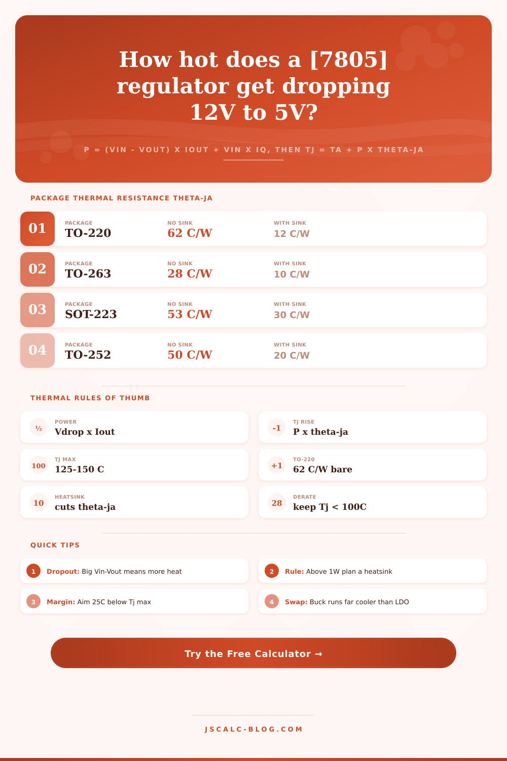
| TO-220 | 62 C/W | 4 C/W | 18 C/W | 8 C/W | 7805, LM317 1A |
| TO-263 D2PAK | 28 C/W | 2 C/W | 16 C/W | 9 C/W | SMD 1 to 3A |
| TO-252 DPAK | 50 C/W | 3 C/W | 28 C/W | 20 C/W | SMD LDO 1A |
| SOT-223 | 53 C/W | 15 C/W | 40 C/W | 30 C/W | AMS1117 800mA |
| SOT-89 | 90 C/W | 25 C/W | 70 C/W | 55 C/W | Small SMD LDO |
| TO-92 | 200 C/W | 83 C/W | 170 C/W | 150 C/W | 78L05 100mA |
| TO-3 metal | 35 C/W | 1.5 C/W | 10 C/W | 4 C/W | High power 5A+ |
🔥Power Dissipation Examples
| Vin to Vout | Load Current | Voltage Drop | Power P | Rise on TO-220 |
|---|---|---|---|---|
| 7V to 5V | 500 mA | 2 V | 1.0 W | 62 C |
| 9V to 5V | 500 mA | 4 V | 2.0 W | 124 C |
| 12V to 5V | 500 mA | 7 V | 3.5 W | 217 C |
| 12V to 5V | 1 A | 7 V | 7.0 W | 434 C |
| 9V to 3.3V | 1 A | 5.7 V | 5.7 W | 353 C |
| 5V to 3.3V | 800 mA | 1.7 V | 1.36 W | 84 C |
| 24V to 5V | 1 A | 19 V | 19 W | needs sink |
| 6V to 5V | 200 mA | 1 V | 0.2 W | 12 C |
Rise shown ignores quiescent current and assumes bare TO-220 at 62 C/W. Values above roughly 100 C rise mean a heatsink or a switching regulator is required.
🌡Junction Temperature Guide
| Junction Temp Tj | Status | What It Means |
|---|---|---|
| Below 60 C | Cool | Plenty of margin, no sink needed |
| 60 to 85 C | Warm | Normal, comfortable to run continuously |
| 85 to 105 C | Hot | Acceptable but add margin if you can |
| 105 to 125 C | Very hot | Near limit, heatsink strongly advised |
| 125 to 150 C | Critical | At or past many datasheet Tj max ratings |
| Above 150 C | Shutdown | Thermal protection trips, output drops out |
⚙Formula Breakdown
💡Practical Cooling Tips
Linear regulators look straightforward. Feed them a big input voltage and they spit out a nice low output voltage. That happens until your design melts down when it’s loaded up. What usually happens? Heat.
Any voltage drop across the regulator chip are wasted energy. This calculator puts a number on that heat for you so you know if bare regulator will handle the job. If not, it tells you if you need a heatsink, or rethink the whole thing. It gives you a clear heat limit in terms of power, headroom and junction temperature.
Why Linear Regulators Get Hot
The math is simple enough and brutal. The power dissipation (the heat produced) are equal to the current consumed by the load times the voltage drop across it. Don’t forget to include a little something extra to account for regulator’s own quiescent draw. Half an amp stepped down from 12 volts to 5 volts? That’s 3.5 watts of pure heat that output cannot offset.
While wattage determines how much heat are generated, temperature is what actualy kills the regulator. More specifically, what matters is junction temperature $T_j$, where the silicon die actualy sits. Thermal resistance connects the die to ambient air. It’s expressed as degrees Celsius per watt.
When you don’t have a heatsink, all these numbers comes together into one: theta-ja, the journey from chip to air. For a bare TO-220 package, it’s roughly 62 degree C per watt. That means adding one watt increase the die temperature by approximately 62 degrees over ambient. Your ambient temperature plus this amount equals estimated die temperature (the calculator assumes your ambient). Subtracting that from typical maximum on the datasheet, typically 125 or 150 degrees C; gives you an estimate of your headroom. If the number is negative, you’ll blow past the safety threshold and trigger the part’s protections.
Thermal resistance of a bare package is higher then that of a setup with a heatsink. Adding a heatsink lowers total thermal resistance. It changes the path from the junction, through the case and thermal paste, into the heatsink and then into the air. In fact, the TO-220 junction-to-case thermal resistance are just a few degrees. Adding a good heatsink may increase that to eleven degrees in all. The total resistance could go from 62 down to less than 17 degrees per watt. At the same 3.5 watt load, the die goes from an unworkable 242 degrees to a reasonable 83 degrees.
You don’t need to do any arithmetic, the tool figures this out automatically so you can observe how the cooling improve. The simplest solution is frequently to reduce waste heat. How much power you toss down the drain determines how hot it gets. Lowering the input voltage closer to output reduces dissipation greatly. Tossing away 1Amp at 7 volts dissipates just 2 watts. Tossing away that same 1 Amp at 12 volts are 7 watts.
Above about a watt, consider a heatsink. At several watts, a switcher like a buck converter will be more efficient then a linear component. That calculator shows these tradeoffs within seconds.
For credible answers, use the actual thermal resistance number from your own datasheet. Your layout and copper pours will change the true answer by some amount; generic numbers won’t be quite right. Ambient should be considered the warmest air within that enclosure. A sealed box warms hotter than a bench, so room temp isn’t a good reference point.
Lastly, target at least 20-25 degrees safety margin under the rating number. That leaves enough space to avoid thermal shutdown. This helps when components is at their worst tolerance and it’s a hot day. Applied in this manner, the tool turns vague heat-related concerns into justifiable engineering choices.