Buck Converter Inductor Value Calculator
Size the power inductor for a step-down (buck) DC-DC converter. Enter input voltage, output voltage, load current, switching frequency and your target ripple-current ratio to get the required inductance in microhenries, the peak-to-peak ripple current, the peak inductor current, and a recommended saturation-current rating for a safe part choice.
⚡Real Buck Design Presets
🔌Converter Inputs
Supply voltage feeding the buck stage.
Regulated rail you want at the load.
Maximum steady load current the rail supplies.
Controller switching frequency in kilohertz.
Peak-to-peak ripple as a percent of Iout. 30% is typical.
Used to estimate input current draw. Leave near 90 if unsure.
Headroom applied to peak current for the Isat rating.
Controls rounding on every result card.
🔢Key Quantities at a Glance
📋Ripple Ratio vs Required Inductance
| Ripple Ratio | dIL at 3A | L for 12V-5V 500kHz | Notes |
|---|---|---|---|
| 20% | 0.60 A | 9.72 uH | Low ripple, bigger L |
| 25% | 0.75 A | 7.78 uH | Quieter output |
| 30% | 0.90 A | 6.48 uH | Common default |
| 35% | 1.05 A | 5.56 uH | Smaller inductor |
| 40% | 1.20 A | 4.86 uH | Higher core loss |
| 50% | 1.50 A | 3.89 uH | Near DCM edge |
📊Switching Frequency vs Required L (12V to 5V, 3A, 30%)
| Frequency | Duty D | dIL | Required L | Peak Current | Isat 1.3x |
|---|---|---|---|---|---|
| 200 kHz | 0.417 | 0.90 A | 16.20 uH | 3.45 A | 4.49 A |
| 300 kHz | 0.417 | 0.90 A | 10.80 uH | 3.45 A | 4.49 A |
| 400 kHz | 0.417 | 0.90 A | 8.10 uH | 3.45 A | 4.49 A |
| 500 kHz | 0.417 | 0.90 A | 6.48 uH | 3.45 A | 4.49 A |
| 800 kHz | 0.417 | 0.90 A | 4.05 uH | 3.45 A | 4.49 A |
| 1 MHz | 0.417 | 0.90 A | 3.24 uH | 3.45 A | 4.49 A |
| 1.5 MHz | 0.417 | 0.90 A | 2.16 uH | 3.45 A | 4.49 A |
| 2 MHz | 0.417 | 0.90 A | 1.62 uH | 3.45 A | 4.49 A |
🧩Common Rails: Sizing Snapshot (30% ripple)
| Vin to Vout | Iout | Freq | Duty D | L needed | Isat 1.3x |
|---|---|---|---|---|---|
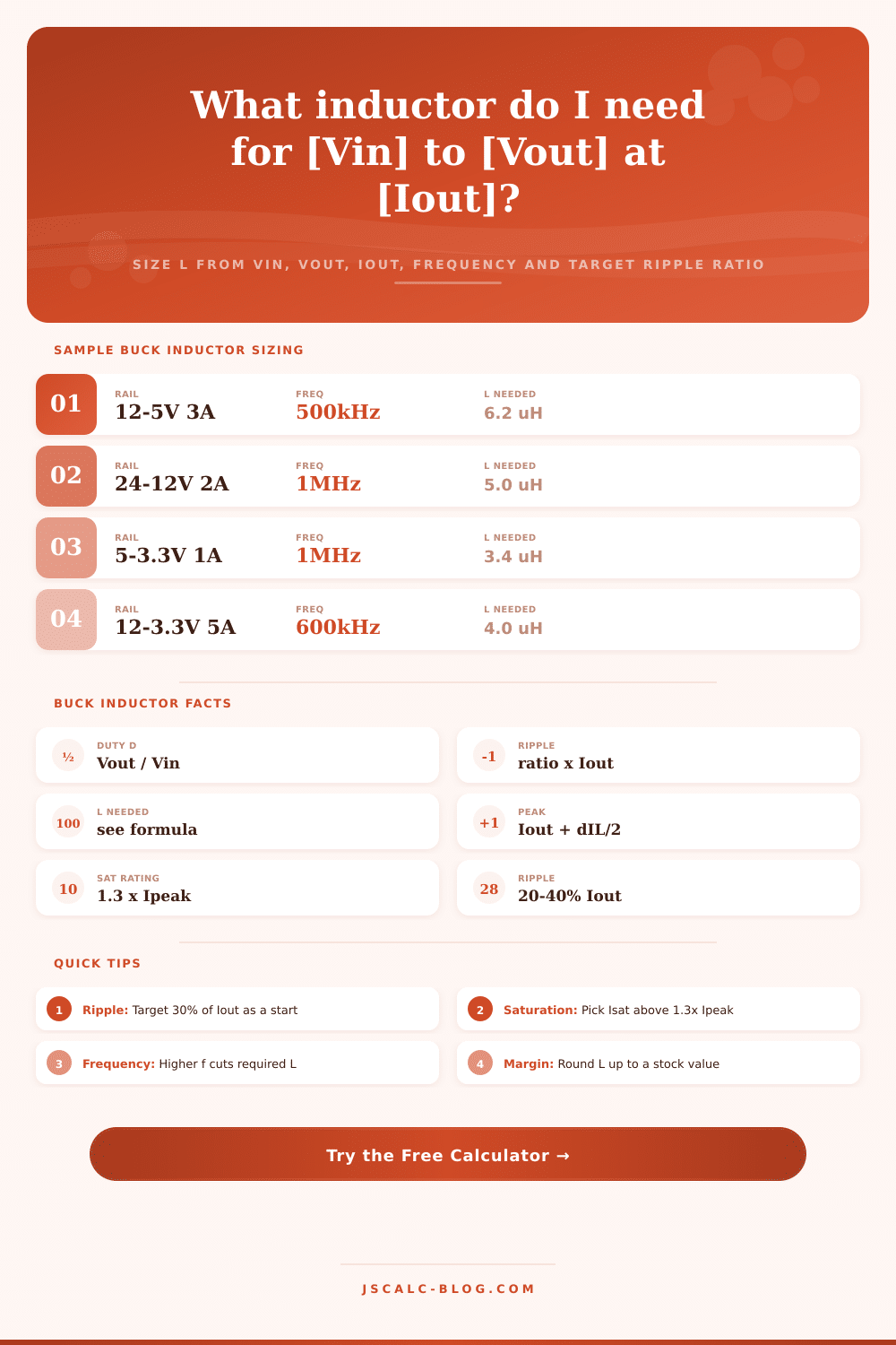
| 12V to 5V | 3 A | 500 kHz | 0.417 | 6.48 uH | 4.49 A |
| 24V to 12V | 2 A | 1 MHz | 0.500 | 5.00 uH | 2.99 A |
| 5V to 3.3V | 1 A | 1 MHz | 0.660 | 3.37 uH | 1.50 A |
| 12V to 3.3V | 5 A | 600 kHz | 0.275 | 3.99 uH | 6.98 A |
| 19V to 5V | 4 A | 400 kHz | 0.263 | 7.68 uH | 5.98 A |
| 12V to 1.2V | 6 A | 800 kHz | 0.100 | 1.50 uH | 8.97 A |
| 48V to 12V | 3 A | 500 kHz | 0.250 | 6.00 uH | 4.49 A |
| 9V to 5V | 2 A | 300 kHz | 0.556 | 7.41 uH | 2.99 A |
⚙Formula Breakdown
💡Inductor Selection Tips
A step-down switching regulator‘s choice of components is highly dependent on the power inductor. It determine how much current can pass through (peak current) and how much current variation will occur (current ripple). It also determines whether the converter will operate in continuous-conduction or discontinuous-conduction mode.
This calculator accepts four known parameters: input voltage, output voltage, load current, and switching frequency. In turn, it outputs the inductance needed, the ripple current, the peak inductor current, and a saturation-current rating. No more guessing at what part to use.
How to Choose the Right Inductor for Your Buck Converter
The inductor is connected between both sides of the buck converter; it charges via the high side (ON) switch from the input and it discharges into the load via the low-side path. During every switching cycle, the current ramps up and down according to a triangular shape. That triangle’s size are determined by value of the inductor.
Too small an inductance makes ripple too large; you need to increase the output capacitor size to level out the voltage, increasing the RMS loss in the traces. Too large a value for the inductor means you get diminishing returns in terms off performance with larger, heavier, more costly parts. Finding the right balance is a question of efficiency, space, and cost: how much do you want to spend? How big can it be?
Duty Cycle This is where it begins: the duty cycle, or the ratio of the output voltage over the input voltage. In an ideal buck regulator, the switch is conducting for this fractional part of each period. If you have a five volt rail from a twelve-volt input, for instance then your duty cycle is approximately forty-two percent. That means the inductor will be charging for that fraction of each cycle and discharging for the remainder of the period.
The tool does the math to determine the on-time percentage; all you have to do is choose what level of ripple current you’re willing to tolerate (at the expense of component size). Engineers express this by how much higher the actual load current can go, calling it “a multiple” of the load current; typical general purpose designs starts around thirty percent. Whatever you plug into the calculator converts that number into an absolute peak-to-peak ripple quantity.
Nine-tenths of an ampere at thirty percent (of a three-ampere load) equals nine-tenths of an ampere of ripple. Twenty percent reduces that ripple, producing a quieter output voltage but requires a physically larger inductor. More core material plus more copper winding. Pushing the ratio upward to forty or fifty percent reduce the size of the magnetic component. However, it also raises the maximum current during each half cycle, which strain the switching transistor and raises core loss because of eddy currents and hysteresis.
Now that we know our duty cycle and ripple targets, we size the inductor using a simple equation that relates allowed ripple to frequency and voltage difference. Here’s where it gets interesting: you’ll see why moddern high-frequency regulators can be built with tiny components. If your controller supports higher frequencies, you double the switching frequency and halve the needed inductance, allowing you to replace a chunky ten-microhenry inductor with a five-microhenry one. This is the main advantage you’ve got when your board space are limited.
That’s just half of it: you need to choose an inductor that won’t saturate when loaded at maximum current, too! Because the current rides the triangle on average, that means the peak is the output current + 1/2 ripple; and the valley is the output. 1/2 ripple. And if the inductor core saturates before that peak, its inductance will collapse dramatically, causing ripple to explode, and the switch can fail completely due to overcurrent. The tool defaults to one-point-three times the calculated peak current, which provides some margin for choosing a saturation-current rating. Then select a catalog inductor whose rated saturation current is greater then this number, but not by much.
A sound design decision involves starting with a ripple target and computing the minimum inductance using the equations. You then confirm the maximum current is within the saturation headroom for a suitable part and round the inductance up to the next highest available stock. Whether you’re validating a reference design or prototyping a new point-of-load regulator, providing the tool with your actual currents and voltages will give you numbers you can trust and order the proper magnetic component comfortabley. Ultimately selecting the correct inductor boils down to achieving a reliable balance of efficiency, size and reliability.