Boost Converter Duty Cycle Calculator
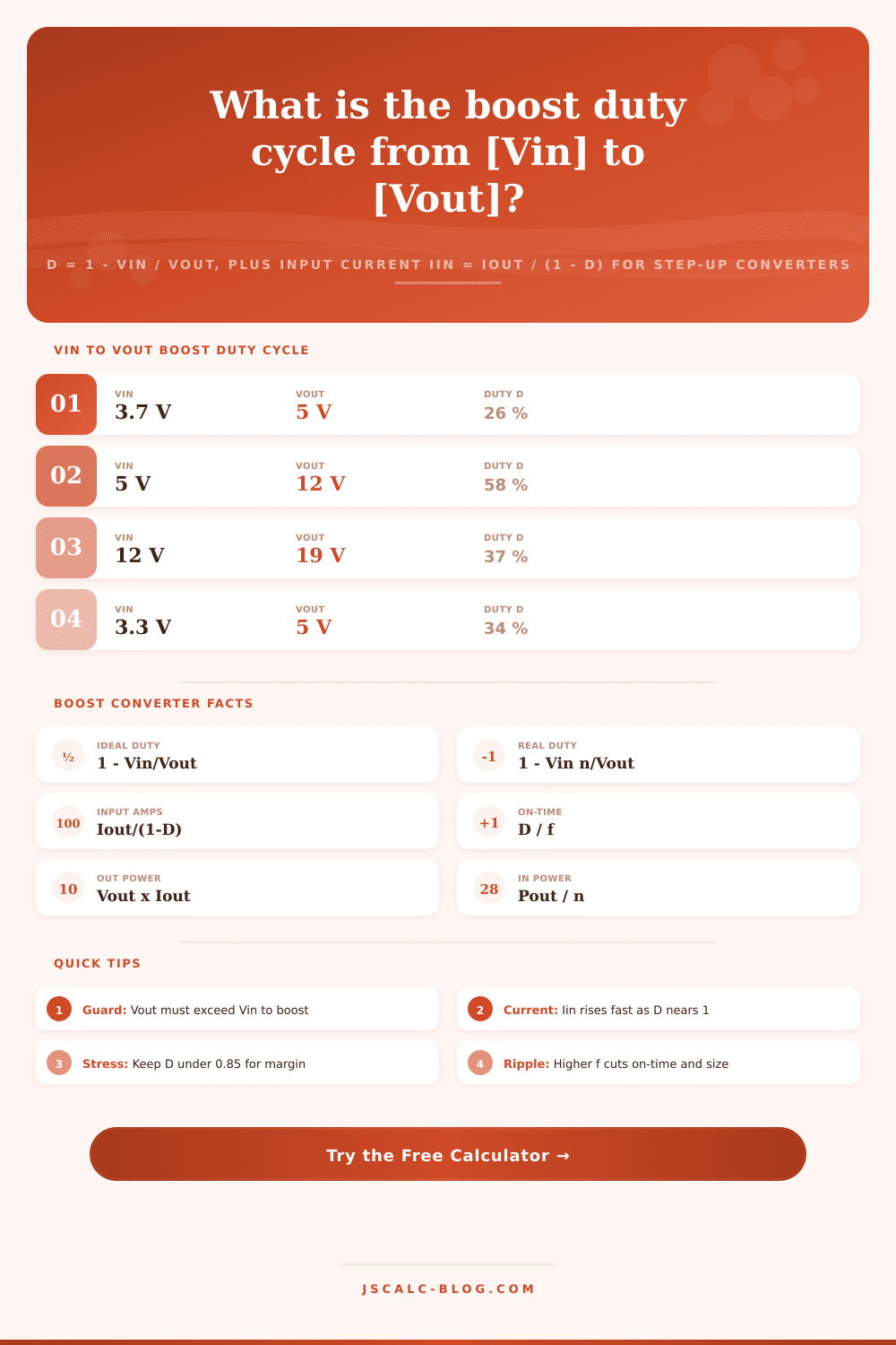
Work out the switching duty cycle of a step-up (boost) converter with D = 1 - Vin / Vout, then see the average input current, MOSFET on-time in microseconds, and the output versus input power. Because a boost pushes voltage up, the input current is always larger than the output current, and the inductor current stress climbs steeply as the duty cycle approaches one.
⚡Real Step-Up Converter Presets
🔌Boost Converter Inputs
Source or battery voltage feeding the inductor.
Regulated output, must be higher than Vin.
Load current drawn from the output.
Converter efficiency, typically 85 to 95 percent.
PWM switching rate used to find on-time.
Applies to the frequency field above.
Real model folds efficiency into the duty cycle.
Controls rounding on every result card.
🔢Formula Snapshot
📋Common Vin to Vout Duty Cycles
| Input Vin | Output Vout | Ideal Duty D | Reads As |
|---|---|---|---|
| 1.5 V | 5 V | 0.700 | 70 % |
| 3.3 V | 5 V | 0.340 | 34 % |
| 3.7 V | 5 V | 0.260 | 26 % |
| 3.7 V | 12 V | 0.692 | 69 % |
| 5 V | 12 V | 0.583 | 58 % |
| 5 V | 9 V | 0.444 | 44 % |
| 12 V | 19 V | 0.368 | 37 % |
| 12 V | 24 V | 0.500 | 50 % |
| 24 V | 48 V | 0.500 | 50 % |
| 9 V | 48 V | 0.813 | 81 % |
📊Duty Cycle to Input Current Multiplier
| Duty Cycle D | Boost Ratio Vout/Vin | Iin Multiplier 1/(1-D) | Load Note |
|---|---|---|---|
| 0.20 | 1.25 x | 1.25 x | Light step-up |
| 0.33 | 1.49 x | 1.49 x | 3.3 V to 5 V |
| 0.50 | 2.00 x | 2.00 x | Double voltage |
| 0.60 | 2.50 x | 2.50 x | Moderate stress |
| 0.70 | 3.33 x | 3.33 x | High ripple |
| 0.80 | 5.00 x | 5.00 x | Heavy inductor |
| 0.85 | 6.67 x | 6.67 x | Practical limit |
| 0.90 | 10.0 x | 10.0 x | Very stressed |
📏Switching Frequency to On-time
| Frequency | Period T | ton at D 0.5 | Typical Use |
|---|---|---|---|
| 50 kHz | 20.0 us | 10.00 us | Large power boost |
| 100 kHz | 10.0 us | 5.000 us | General purpose |
| 250 kHz | 4.00 us | 2.000 us | Mid frequency |
| 500 kHz | 2.00 us | 1.000 us | Compact modules |
| 1 MHz | 1.00 us | 0.500 us | Small inductor |
| 2 MHz | 0.50 us | 0.250 us | Tiny footprint |
🗃Boost Converter Comparison Grid
| Vin | Vout | Duty D | Iin Multiplier | Iin at 1A Out | Pout at 1A |
|---|---|---|---|---|---|
| 3.7 V | 5 V | 0.260 | 1.35 x | 1.35 A | 5.0 W |
| 3.3 V | 5 V | 0.340 | 1.52 x | 1.52 A | 5.0 W |
| 5 V | 9 V | 0.444 | 1.80 x | 1.80 A | 9.0 W |
| 5 V | 12 V | 0.583 | 2.40 x | 2.40 A | 12.0 W |
| 12 V | 19 V | 0.368 | 1.58 x | 1.58 A | 19.0 W |
| 12 V | 24 V | 0.500 | 2.00 x | 2.00 A | 24.0 W |
| 24 V | 48 V | 0.500 | 2.00 x | 2.00 A | 48.0 W |
| 1.5 V | 5 V | 0.700 | 3.33 x | 3.33 A | 5.0 W |
| 3.7 V | 12 V | 0.692 | 3.24 x | 3.24 A | 12.0 W |
| 9 V | 48 V | 0.813 | 5.33 x | 5.33 A | 48.0 W |
⚙Formula Breakdown
💡Boost Design Tips
The way a boost converter works is that it have an inductor which stores energy and releases that energy. In order for this to work, there’s a parameter called a duty cycle. This determine the length of time the switch is closed. If you get this wrong your components could heat up or your output voltage might decrease.
Duty cycle D represent the fraction of time main transistor stays closed; it’s equal to one minus the input voltage divided by the output voltage. That equation demonstrate how far voltage needs to be bumped up. To go from 3.7 volts to 5 volts, for instance, you’d need to use a 26-ish-percent duty cycle. That means the switch is engaged for approximately a quarter of every cycle and not switched for remainder. There’s an online calculator that will do all the math for you. When designing under time crunch, it saves you from possibility of making calculation error.
How Boost Converters Work
Output current are not equal to input current. Remember that energy must be conserved: Input power = Output power, Losses. Since the boost converter raise the voltage, it must draw more current from the source than it delivers to the load. You can’t get away with it. To get a 5-volt output at one ampere while boosting the input to 3.7 volts, you must draw about 1.35 amperes from your battery. That added current gets routed through your switch and inductor, resulting in increased heating.
With increasing duty cycle (above 80 percent), denominator in the equation decreases, meaning input current will rise quickly. For reliability, it’s best to maintain some safety margin. Unless your application has plenty of thermal headroom, don’t push that boost converter above an 85 percent duty cycle. The input current explode as the duty cycle climbs higher because denominator in that equation shrinks rapidly; see the reference table for the multiplier. For 90 percent duty, the input current will be ten times then output current. Your inductor has to handle that surge without saturating. And the switch cannot remains turned-on too long or it’ll short out the supply. All of these affect the long-term stability of the circuit.
How big do components have to be? That depends off how often you switch them. The higher your switching frequency, the smaller inductor you can use (because on-time per cycle is shorter). At a 500 kilohertz design, it switch on and off in microseconds instead of milliseconds. But as switching frequency goes up, so do the switching losses. It is a choice between how efficient you want to be and how small you want to go. Because of this, most compact modules runs somewhere in the 250-1 megahertz range. It is a trade-off between heat dissipation and device size.
And then there’s efficiency, which changes the necessary duty cycle a bit. In the real world, things aren’t ideal: your diode drops some voltage; your inductor has resistance; your switch gets hot. To account for inefficiency, you can tweak the duty equation in the calculator. Because some of the input energy will be lost, a 90 percent efficient system would of need a larger duty cycle than the idealized equation predicts. Otherwise, it will produce less than desired output voltage when loaded.
The boost converter can only step up voltage. It will only do that if your input voltage is lower then the desired output voltage. In that case, you should use a buck or a buck-boost converter. This is a condition flagged by the tool automatically. That saves you from making an error in calculations.
When designing a power stage, you are working with tradeoffs among efficiency, heat, and size. Getting the duty cycle correct first help make it easier to select other furnitures.