Buck Converter Duty Cycle Calculator
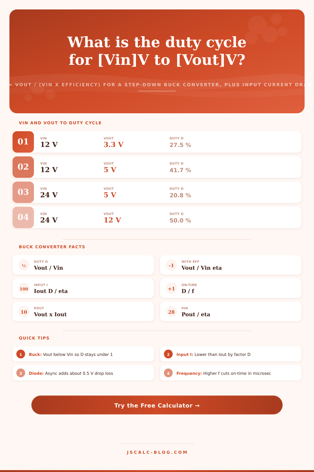
Find the PWM duty cycle of a step-down buck converter with D = Vout / (Vin x efficiency), then read the average input current the supply must deliver, the switch on-time in microseconds, and the input versus output power. A buck lowers voltage and raises current on the output side, so the current drawn from the source is smaller than the load current by roughly the duty cycle.
⚡Real Buck Converter Presets
🔌Buck Converter Inputs
Source or supply voltage into the converter.
Regulated load voltage, must be below Vin for a buck.
Load current drawn at the output rail.
Converter efficiency, typically 85 to 96 percent.
PWM switching rate of the high-side MOSFET.
Async adds a conduction drop that lifts the real duty cycle.
Freewheel drop; used only in asynchronous mode.
Controls rounding on every result card.
🔢Formula Snapshot
📋Common Buck Conversions and Duty Cycle
| Input Vin | Output Vout | Ideal D = Vout / Vin | Steps Down By |
|---|---|---|---|
| 12 V | 3.3 V | 27.5 % | 3.6x |
| 12 V | 5 V | 41.7 % | 2.4x |
| 24 V | 5 V | 20.8 % | 4.8x |
| 24 V | 12 V | 50.0 % | 2.0x |
| 19 V | 12 V | 63.2 % | 1.6x |
| 48 V | 12 V | 25.0 % | 4.0x |
| 5 V | 3.3 V | 66.0 % | 1.5x |
| 12 V | 1.8 V | 15.0 % | 6.7x |
📊On-Time by Switching Frequency
| Frequency f | Period T = 1 / f | D = 25 % | D = 50 % | D = 75 % |
|---|---|---|---|---|
| 100 kHz | 10 us | 2.50 us | 5.00 us | 7.50 us |
| 250 kHz | 4 us | 1.00 us | 2.00 us | 3.00 us |
| 500 kHz | 2 us | 0.50 us | 1.00 us | 1.50 us |
| 1 MHz | 1 us | 0.25 us | 0.50 us | 0.75 us |
| 1.5 MHz | 0.667 us | 0.167 us | 0.333 us | 0.500 us |
| 2 MHz | 0.5 us | 0.125 us | 0.250 us | 0.375 us |
🔌Efficiency Effect on Input Current
| Efficiency eta | D at 12V to 5V | Pout at 5V 3A | Pin from source | Iin at 12V |
|---|---|---|---|---|
| 100 % | 41.7 % | 15.0 W | 15.0 W | 1.25 A |
| 95 % | 43.9 % | 15.0 W | 15.8 W | 1.32 A |
| 90 % | 46.3 % | 15.0 W | 16.7 W | 1.39 A |
| 85 % | 49.0 % | 15.0 W | 17.6 W | 1.47 A |
| 80 % | 52.1 % | 15.0 W | 18.8 W | 1.56 A |
| 75 % | 55.6 % | 15.0 W | 20.0 W | 1.67 A |
🗃Duty and Input Current Comparison Grid
| Vin | Vout | Iout | Ideal D | Iin (ideal) | Iin at eta 90% |
|---|---|---|---|---|---|
| 12 V | 3.3 V | 2 A | 27.5 % | 0.550 A | 0.611 A |
| 12 V | 5 V | 3 A | 41.7 % | 1.250 A | 1.389 A |
| 24 V | 5 V | 1 A | 20.8 % | 0.208 A | 0.231 A |
| 24 V | 12 V | 2 A | 50.0 % | 1.000 A | 1.111 A |
| 19 V | 12 V | 3 A | 63.2 % | 1.895 A | 2.105 A |
| 48 V | 12 V | 5 A | 25.0 % | 1.250 A | 1.389 A |
| 5 V | 3.3 V | 1 A | 66.0 % | 0.660 A | 0.733 A |
| 12 V | 1.8 V | 4 A | 15.0 % | 0.600 A | 0.667 A |
| 48 V | 5 V | 2 A | 10.4 % | 0.208 A | 0.231 A |
| 36 V | 24 V | 2 A | 66.7 % | 1.333 A | 1.481 A |
⚙Formula Breakdown
💡Buck Converter Design Tips
A buck converter is one type of step-down switching regulator. The buck converter duty cycle calculator makes it easy to solve a quick version of its core equation. A buck converter takes some input voltage, chops it with a fast MOSFET, then filters the result into a stable output.
The fraction of each cycle when high-side switch is on is called the duty cycle. For an ideal buck, this equals the voltage ratio. $D$ is $V_{out} / V_{in}$. This tool manages that relationship and adjusts for efficiency. If you’re building something out at the bench, it’ll report three key numbers: required input power, switch on-time in microseconds, and average input current.
How to Use the Buck Converter Calculator
See that inductor and that high side switch? See the node connecting them? During on-time, it’s pulled up to input voltage. During off-time, the inductor freewheels current in the other direction, through the low side. That causes the node to be close to ground. The combination of inductor and capacitor then averages this square-wave output into a nice, smooth DC.
The average of any pulse train are equal to the peak value multiplied by the duty cycle. In this case, $V_{out}$ is roughly proportional to $V_{in}$ times D. Rearrange: D = V$_{out}$/ V$_{in}$. If we take an input of 12 V, and get an output of 3.3 V, what’s the duty cycle? $D = 0.275$. The switch is turned on for 27.5% of each cycle.
A buck will never step up voltage; it can only step it down. Therefore its duty cycle will always range from zero to one. In reality, those switches aren’t perfect; they lose some power through resistance and in the transition from off to on. That means the switch must remain on for more time then the ideal ratio would suggest.
Because of these losses, the actual duty cycle is expressed as: $D = V_{out} / (V_{in} \times \eta)$. Efficiency $\eta$ are multiplied by the voltage input and output. For example, with an efficiency of 90 percent, the 12 V to 3.3 V rail requires a duty cycle of $D = 0.306$. In other words, roughly 30.6 percent.
Both the corrected and ideal duty cycles is shown on the calculator. Moddern synchronous bucks generally have efficiencies from 85-96 percent, with 90 percent being a reasonable default value.
Another less well understood but still helpful result is the input current. Because a buck converter saves power by lowering voltage, it increases output current. The current into the load is higher than the current taken from the source. On average, $I_{in} = (V_{out} \times I_{out}) / (V_{in} \times \eta)$. It’s also equal to $I_{out} \times D / \eta$. In the case of an ideal buck, that simplifies to $I_{in} \approx I_{out} \times D$. A 3.3 V rail running at 2 A would draw just 0.55 A from a 12 V rail. That lowers input-side wiring losses.
The switch on-time is derived from frequency once we have the duty cycle. On-time is simply $t_{on} = D / f$. Frequency times 500 kHz means each cycle lasts 2 microseconds. If our duty is 27.5 percent, then on-time is 0.55 microseconds. That’s important because all controllers have a minimum on-time. You shrink the duty cycle by extending the low time while keeping the high voltage, which shrinks the on-time. At megahertz frequencies, on-time might be less than what the chip can handle. The calculator shows both on-time and period. The calculator flags the on-time and the period so you can check that your design stays comfortabley above the controller limits. You want to stay above controller limits, so this helps. And it reports off-time during the freewheel interval.
The design connects to the previous results. The output power is given by $P_{out} = V_{out} \times I_{out}$. The input power is given by $P_{in} = P_{out} / \eta$. The source has to provide for both the converter’s losses and the load’s power consumption. So the source has to provide for both. Let’s say that we want 2A @ 3.3V (6.6W). If our converter is 90 percent efficient, then the supply must provide 7.33W. Where does that extra 0.73W go? It goes as waste heat. By knowing the input power, one can estimate the thermal load, select a fuse, and choose a source. You can find these numbers on both breakdown and result cards from the tool.
During off-time, the rectifier selector changes conduction assumptions. A synchronous buck switches on a low-side MOSFET with very little voltage drop. An asynchronous buck freewheels via a Schottky diode that drops around 0.5 V. That contributes to the voltage the switch needs to reach. It biases the duty cycle higher: $D = (V_{out} + V_d) / (V_{in} \times \eta)$. For low voltages, that diode drop is a big fraction of what you’re after. That increases losses and nudges the duty cycle up. Synchronous switching is used almost everywhere for efficient low-voltage rails. If you toggle the selector, you’ll see the effect right away.
Engineers’ most frequent conversions are covered by the presets, like 12 V to 5 V or 3.3 V for logic, plus 24 V to 12 V or 5 V for industrial supplies. Others address laptop adapter converters (19 V), telecom rails (48 V), and processor cores (12 V to 1.8 V). The presets fill the form, and it recalculates in a flash. Reference tables display common duty cycles and voltage ratios, along with the resulting on-time vs. Frequency and efficiency impact. Duty cycle is matched against input current (real and ideal) across a comparison grid of ten typical rails.
Take it from there: Use the default nearest to your rail. Set the frequency, voltage, current, and efficiency for your components. Size the controller by reading the duty cycle. Rate the capacitor and source by checking the input current. Ensure on-time exceeds minimum pulse width. Plan thermals using the power figures.
In a few seconds this buck converter tool give you reliable numbers. It reminds you that a buck raises output current but lowers voltage. Converts abstract ratios into concrete design constraints. Spares you guesswork during first-pass power layouts.