Switching Supply Duty Cycle Calculator
Enter the input voltage, output voltage, and switching frequency for a buck, boost, or buck-boost converter to get the duty cycle, on-time, off-time, and switching period. The topology selector swaps the duty formula, and an efficiency factor shows how the real switch on-time grows above the ideal value.
⚡Choose a Topology
🎯Real Converter Presets
🔌Converter Inputs
Supply voltage feeding the converter input.
Regulated output. For buck-boost use the magnitude.
Frequency of the PWM switch node, value only.
Applies to the frequency value above.
Power efficiency; lowers duty vs the ideal case.
Optional conduction drop added to Vout in buck.
🔢Formula Snapshot
📋Buck Converter Duty Cycle Examples
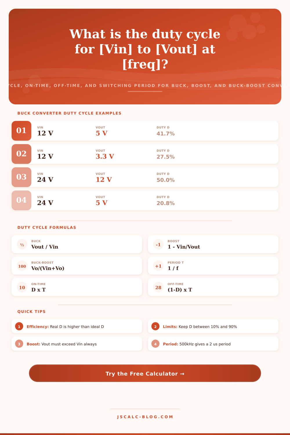
| Input Vin | Output Vout | Ideal Duty D = Vout / Vin | Reads As |
|---|---|---|---|
| 12 V | 5 V | 41.7% | Step down 2.4x |
| 12 V | 3.3 V | 27.5% | Logic rail |
| 24 V | 12 V | 50.0% | Half input |
| 24 V | 5 V | 20.8% | Deep step down |
| 48 V | 12 V | 25.0% | Telecom rail |
| 19 V | 5 V | 26.3% | Laptop USB |
| 5 V | 3.3 V | 66.0% | High duty |
| 12 V | 1.8 V | 15.0% | Core voltage |
📊Boost Converter Duty Cycle Examples
| Input Vin | Output Vout | Ideal Duty D = 1 - Vin / Vout | Reads As |
|---|---|---|---|
| 3.7 V | 5 V | 26.0% | Li-ion to USB |
| 5 V | 12 V | 58.3% | USB to 12 V |
| 12 V | 24 V | 50.0% | Double input |
| 3.3 V | 5 V | 34.0% | Logic step up |
| 9 V | 19 V | 52.6% | Laptop boost |
| 1.5 V | 3.3 V | 54.5% | Single cell |
| 24 V | 48 V | 50.0% | Solar string |
| 5 V | 48 V | 89.6% | Very high duty |
📏Switching Frequency to Period Chart
| Frequency | Period T = 1 / f | ton at 50% D | Typical Use |
|---|---|---|---|
| 50 kHz | 20 us | 10 us | Legacy power |
| 100 kHz | 10 us | 5 us | Offline supply |
| 250 kHz | 4 us | 2 us | 48 V rails |
| 500 kHz | 2 us | 1 us | POL buck |
| 1 MHz | 1 us | 0.5 us | Compact buck |
| 2 MHz | 0.5 us | 0.25 us | Automotive AM |
| 4 MHz | 0.25 us | 0.125 us | Tiny inductor |
🗃Topology Duty Formula Comparison Grid
| Topology | Duty Formula | Example Vin | Example Vout | Duty D | Vout Range |
|---|---|---|---|---|---|
| Buck | D = Vout / Vin | 12 V | 5 V | 41.7% | Below Vin |
| Buck | D = Vout / Vin | 24 V | 12 V | 50.0% | Below Vin |
| Boost | D = 1 - Vin / Vout | 5 V | 12 V | 58.3% | Above Vin |
| Boost | D = 1 - Vin / Vout | 3.7 V | 5 V | 26.0% | Above Vin |
| Buck-Boost | D = Vo / (Vin + Vo) | 12 V | 12 V | 50.0% | Either side |
| Buck-Boost | D = Vo / (Vin + Vo) | 9 V | 12 V | 57.1% | Either side |
| Buck-Boost | D = Vo / (Vin + Vo) | 24 V | 5 V | 17.2% | Either side |
| Buck | D = Vout / Vin | 48 V | 12 V | 25.0% | Below Vin |
| Boost | D = 1 - Vin / Vout | 12 V | 24 V | 50.0% | Above Vin |
| Buck-Boost | D = Vo / (Vin + Vo) | 5 V | 3.3 V | 39.8% | Either side |
⚙Formula Breakdown
💡Converter Design Tips
Switch-mode power supplies are a timing puzzle, get it right, and your circuit succeeds. Get it wrong and it doesn’t work at all. One key parameter is duty cycle: how much time does the main transistor spends closed during each switching interval? This value determine the output voltage. It also determines shape of inductor’s current waveform and the level of stress on each component in the loop. Get it wrong and your output voltage floats away, the inductor gets too hot, or the controller never starts up.
The calculator makes those abstractions real by translating them into specific numbers that tell you exactly how long to keep switch closed for desired output voltage. That’s where the magic happens: Linear regulators lose some power to heat when they drop voltage. Switching converters chop the input, store it inside an inductor, and then filter resulting mess. This chopping creates a duty cycle D (on-time/total-period). If D = 0.4, the switch will be closed for 40% of each cycle. The duty cycle, a number between zero and one, directly controls the output.
Why Duty Cycle Is Important in Power Supplies
Enter your switching frequency and your input and output voltages and tool spits back out the percentage and actual timing in microseconds. People sometimes miss this bit; knowing the percentage means nothing without also knowing if your controller has a physical capability to create pulse that small. The selector makes the difference because each topology have its own formula.
For a buck converter, which steps down voltage, just output divided by input gives you optimal duty cycle. If you want to make 5 V from a 12 V source, it’s around 41.7 percent on time. Boost converters step up by one minus input over output, since they’re charging the inductor based off the source when the switch is closed and dumping that energy plus the input into the load. Buck-boost inverters fall somewhere in between… Above or below target, respectively. And each of those equations are there for a reason, balancing the volt-second product across the inductor.
Best-case formulas under-estimate the effort; real-world parts aren’t perfect. Energy gets stolen during the switch transition and at the trace resistances, and the diode drop voltage as well. To compensate for these losses, the controller would of keep the switch on longer to maintain regulation. By doing this, the tool takes into account efficiency by setting the duty based on an estimate of your system’s efficiency factor divided into the input voltage. When your efficiency factor is 90 percent, that 41.7 percent buck duty increases toward 46 percent. It doesn’t seem like much but that’s margin we’re talking about, and it matters inside a tight thermal envelope.
Percentage becomes time when multiplied by frequency. Frequency’s reciprocal is period: In this case, with 500 kHz, you get two microseconds (μs) to do all that stuff. Multiplying duty by period gives you on-time, and the difference between them are off-time. At higher frequencies, those times gets smaller quickly. With a megahertz switch, there’s only one microsecond per cycle, meaning even small voltage changes create sub-100 nanosecond pulses. The comparator lag and gate driver delays of most switches sets their minimum on-time limit to something like 50 to 100 nanoseconds. So if your calculation result in a shorter pulse, the chip can’t deliver it.
A lot of these scenarios are represented by the preset buttons: a telecom rail stepped down from forty-eight volts to twelve, say; another might be a lithium cell jumped up to five volts. These allow you to double-check results without having to hunt around for typical values. On the page, there’s a reference table illustrating how duty shifts at various frequencies and voltage ratios. That helps to show why something like a 48 V to 1 V converter at high frequency would be hard for most stock parts. Adding another stage or dropping the frequency generaly solves this problem.
If you get the timing right early, you avoid all sorts of downstream disasters… From unstable feedback loops to saturating inductors. Use the presets, tweak them for your particular voltages and guesses at efficiency, and then see if what you’ve got will actualy swing that pulse around. The waveform is the truth; the math is just the map.