Free Space Path Loss Calculator
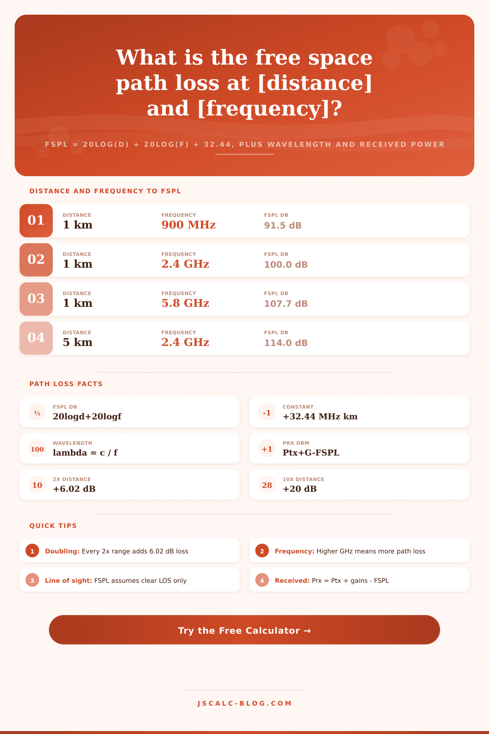
Compute free space path loss with the Friis equation FSPL = 20 log10(d) + 20 log10(f) + 32.44, using distance in meters, kilometers, or miles and frequency in MHz or GHz. The tool also returns the wavelength and, when you supply transmit power and antenna gains, the received power in dBm from Prx = Ptx + Gtx + Grx minus FSPL.
📡Real Radio Link Presets
🔧Link Inputs
Path length (line of sight) from transmitter to receiver.
1 mi = 1.609344 km; converted internally.
Carrier frequency of the radio signal.
1 GHz = 1000 MHz; applies to the field above.
Leave blank to skip the received power card. 30 dBm = 1 W.
Isotropic is 0 dBi; a typical panel is 6 to 18 dBi.
Gain of the receiving antenna in dBi.
Cable, connector, and misc losses subtracted from Prx.
Controls rounding on every result card.
🔢Formula Snapshot
📋FSPL by Distance and Frequency
| Distance | Frequency | FSPL (dB) | Typical Use |
|---|---|---|---|
| 100 m | 2.4 GHz | 80.0 dB | Indoor Wi-Fi |
| 1 km | 900 MHz | 91.5 dB | Cellular cell |
| 1 km | 2.4 GHz | 100.0 dB | Wi-Fi bridge |
| 1 km | 5.8 GHz | 107.7 dB | PtP backhaul |
| 5 km | 2.4 GHz | 114.0 dB | Long Wi-Fi link |
| 10 km | 868 MHz | 111.2 dB | LoRa telemetry |
| 20 km | 5.8 GHz | 133.7 dB | Microwave PtP |
| 20200 km | 1.575 GHz | 182.5 dB | GPS downlink |
📊Distance Scaling Reference
| Distance Change | Frequency Change | FSPL Change | Why | Example |
|---|---|---|---|---|
| 2x farther | Same | +6.02 dB | 20 log10(2) | 1 to 2 km |
| 3x farther | Same | +9.54 dB | 20 log10(3) | 1 to 3 km |
| 5x farther | Same | +13.98 dB | 20 log10(5) | 1 to 5 km |
| 10x farther | Same | +20.00 dB | 20 log10(10) | 1 to 10 km |
| Same | 2x higher | +6.02 dB | 20 log10(2) | 2.4 to 4.8 GHz |
| Same | 10x higher | +20.00 dB | 20 log10(10) | 900 MHz to 9 GHz |
| Half as far | Same | -6.02 dB | 20 log10(0.5) | 2 to 1 km |
📶Band, Wavelength, and Constant
| Band | Frequency | Wavelength | Constant (km) | Note |
|---|---|---|---|---|
| ISM 433 | 433 MHz | 0.692 m | +32.44 (MHz) | Remote controls |
| LoRa EU | 868 MHz | 0.345 m | +32.44 (MHz) | IoT sensors |
| GSM 900 | 900 MHz | 0.333 m | +32.44 (MHz) | 2G cellular |
| Wi-Fi 2.4 | 2.4 GHz | 0.125 m | +92.45 (GHz) | Wi-Fi, BT |
| Wi-Fi 5 | 5.8 GHz | 0.052 m | +92.45 (GHz) | Wi-Fi, PtP |
| Ku band | 12 GHz | 0.025 m | +92.45 (GHz) | Satellite TV |
🗃FSPL Comparison Grid (dB)
| Distance | 433 MHz | 900 MHz | 2.4 GHz | 5.8 GHz | 12 GHz |
|---|---|---|---|---|---|
| 100 m | 65.2 | 71.5 | 80.0 | 87.7 | 94.0 |
| 500 m | 79.2 | 85.5 | 94.0 | 101.7 | 108.0 |
| 1 km | 85.2 | 91.5 | 100.0 | 107.7 | 114.0 |
| 2 km | 91.2 | 97.5 | 106.0 | 113.7 | 120.0 |
| 5 km | 99.2 | 105.5 | 114.0 | 121.7 | 128.0 |
| 10 km | 105.2 | 111.5 | 120.0 | 127.7 | 134.0 |
| 20 km | 111.2 | 117.5 | 126.0 | 133.7 | 140.0 |
| 50 km | 119.2 | 125.5 | 134.0 | 141.7 | 148.0 |
⚙Formula Breakdown
💡Path Loss Planning Tips
Why? Because radio waves is like water flowing off side of a bucket: They expand as they go; they thin out to nothing in background noise. And that’s the nature of geometry, not a flaw in the gear. That’s what free space path loss, or FSPL, measure: the math on how far signal spreads as it travels from antenna. How many watts it lose as it expands beyond the antenna across a bigger and bigger sphere.
The calculator will do all that math for you above. Enter frequency and distance. It spits out answer in plain old decibels, which is what you need to know to figure out whether your link is doable before buying any gear. Two variables are needed for this equation: Frequency and distance. The latter’s easy enough, it’s how far away you’re measuring. The first part trips many people up. Frequency carries more information, but it does so much faster at the high end of band then at the low end. So you put in your distance (miles, kilometers, or meters), and your frequency (gigahertz or megahertz). Don’t worry about units not matching, though… The calculator will convert them for you. Then it use the constant, typically 32.44 if your inputs is in megahertz and kilometers, and spits out answer.
How to Use the Free Space Path Loss Calculator
But this isn’t about the number; it’s about what you’re going to do with it. Sending power or antenna gain is how you pay for path loss (which is a cost, not a barrier). So when you calculate that your signal attenuates by one-hundred decibel between points A and B, but your radio can only hears signals down to minus ninety decibels, then you’ve got a problem. That’s why we included fields for antenna gains at either end, along with transmit power. This allows the calculator to work out receive power directly. Add your gains, subtract the path loss, and see if it exceed the sensitivity threshold of receiver. In other words: turn abstract physics into a practical budget.
Intuition can catch up with the math with a simple rule of thumb: you lose roughly six decibels every time you double the distance. That’s true for free space path loss, which scales logarithmically. So while going from one kilometer to two cost very little in signal strength, going from ten to twenty will be costly. The same goes for frequency: you lose six decibels every time you double the frequency. Indoor access points operates at five gigahertz, while cellular operates around nine hundred megahertz. The lower frequency doesn’t suffer as much of that spreading penalty, allowing it to penetrate buildings more effectively.
But there’s no such thing as a straight line of sight in real life: trees will block signal, rain absorbs it, and the atmosphere itself will rob some of the power that FSPL doesn’t factor in. Engineers typically includes a fade margin to compensate for unknowns. This margin is typically between ten and twenty decibels. So if you’re looking at your calculator and seeing “just enough,” you likely do not: you’ll want some headroom.
This is where the built-in presets in the tool realy work. They show just how far a signal has to travel from space down to Earth to reach a GPS receiver, losing almost one-hundred-and-eighty decibels along the way. Seems unlikely… but remember, those satellite dishes have huge gains, and those receivers are super-sensitive. Those trade offs is what save people money and headaches. They help avoid the all-too-common mistake of turning up the transmit power if all that’s really needed is a better antenna. You should of used more gain. It lets you decide which band to use based off range or data rates. Longer ranges require lower frequencies. Higher frequencies has more bandwidth, making them good for short ranges and high data rates.
Use the calculator as your starting point, then put in the context from there. After a while you realize just how fast those dBs accumulate and design around physics instead of against them.