Antenna Beamwidth Calculator
Find the half-power beamwidth (HPBW) of a parabolic dish or aperture antenna from its diameter and operating frequency. Use a single round aperture, or enter separate width and height to get the E-plane and H-plane beamwidths, plus an estimated peak gain in dBi from the beam solid angle.
📡Choose an Aperture Type
🎯Real Antenna Presets
🔧Antenna Inputs
Center frequency of the antenna in the unit at right.
Wavelength is found as lambda = c / f.
Physical dish diameter, in the length unit at right.
Horizontal size sets the H-plane beamwidth.
Vertical size sets the E-plane beamwidth.
Applies to diameter, width and height.
Edge taper widens the beam and raises the constant k.
HPBW = k x lambda / D. 58 uniform, 70 typical.
Used only for the gain estimate, typically 55 to 70.
Controls rounding on every result card.
🔢Formula Snapshot
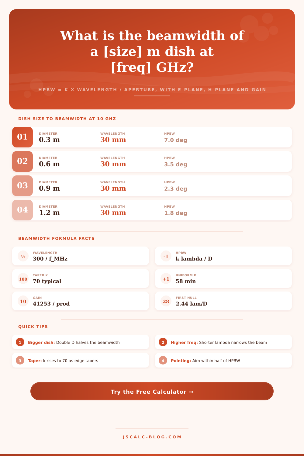
📡Dish Diameter to HPBW at 10 GHz
| Diameter D | Wavelength | HPBW (k = 70) | Reads As |
|---|---|---|---|
| 0.3 m | 30 mm | 7.00 deg | Wide beam |
| 0.6 m | 30 mm | 3.50 deg | Broad |
| 0.9 m | 30 mm | 2.33 deg | Moderate |
| 1.2 m | 30 mm | 1.75 deg | Narrow |
| 1.8 m | 30 mm | 1.17 deg | Narrow |
| 2.4 m | 30 mm | 0.88 deg | Tight |
| 3.0 m | 30 mm | 0.70 deg | Pencil |
| 6.0 m | 30 mm | 0.35 deg | Pencil |
📊Beamwidth Constant by Illumination
| Illumination | Constant k | Edge Taper | First Sidelobe | Typical Use |
|---|---|---|---|---|
| Uniform | 58 | 0 dB | -13 dB | Theoretical min |
| Light taper | 65 | -6 dB | -20 dB | High-gain feeds |
| Typical dish | 70 | -10 dB | -24 dB | Most reflectors |
| Cosine taper | 72 | -12 dB | -23 dB | Horns |
| Heavy taper | 73 | -15 dB | -30 dB | Low sidelobe |
| Gaussian | 75 | -18 dB | -35 dB | Radio astronomy |
| Cosine squared | 83 | -25 dB | -42 dB | Very low lobe |
📏Frequency Band Wavelengths
| Band | Frequency | Wavelength | Common Use |
|---|---|---|---|
| UHF | 432 MHz | 694 mm | EME, amateur |
| L-Band | 1.5 GHz | 200 mm | GPS, satcom |
| S-Band | 2.4 GHz | 125 mm | WiFi, radar |
| C-Band | 4 GHz | 75 mm | Satellite TV |
| Ku-Band | 12 GHz | 25 mm | VSAT, DBS |
| Ka-Band | 30 GHz | 10 mm | HTS satcom |
| V-Band | 60 GHz | 5 mm | mmWave links |
| W-Band | 94 GHz | 3.2 mm | Cloud radar |
🗃Aperture and Frequency Beamwidth Comparison Grid
| Aperture D | Frequency | Wavelength | HPBW (k = 70) | First Null BW | Est. Gain |
|---|---|---|---|---|---|
| 0.6 m | 12 GHz | 25 mm | 2.92 deg | 5.83 deg | 35.5 dBi |
| 1.2 m | 12 GHz | 25 mm | 1.46 deg | 2.91 deg | 41.5 dBi |
| 1.8 m | 12 GHz | 25 mm | 0.97 deg | 1.94 deg | 45.0 dBi |
| 2.4 m | 4 GHz | 75 mm | 2.19 deg | 4.37 deg | 38.0 dBi |
| 3.0 m | 6 GHz | 50 mm | 1.17 deg | 2.33 deg | 43.4 dBi |
| 0.3 m | 24 GHz | 12.5 mm | 2.92 deg | 5.83 deg | 35.5 dBi |
| 0.9 m | 60 GHz | 5 mm | 0.39 deg | 0.78 deg | 52.9 dBi |
| 34 m | 8.4 GHz | 35.7 mm | 0.073 deg | 0.147 deg | 68.0 dBi |
| 1.0 m | 5.8 GHz | 51.7 mm | 3.62 deg | 7.24 deg | 33.6 dBi |
| 4.5 m | 10 GHz | 30 mm | 0.47 deg | 0.93 deg | 51.4 dBi |
⚙Formula Breakdown
💡Pointing and Link Tips
Getting your dish pointed is a tricky business, especially the first time you try. That’s because your margin of error might be smaller than a quarter held at arm’s length. This happens while you’re trying to find a signal from something 30 thousand miles away. So, you’ve got a receiver out there looking for a needle in a haystack and if you are off by a fraction of a degree, then the needle vanishes back into the noise.
This is when beamwidth gets real-world practical; will you make the link, or not? The answer lie in the half-power beamwidth (HPBW), which is the width of the invisible target your antenna aims at. In other words, HPBW describes the angular cone within which your antenna catches the majority of the power. It also include the points where the signal drops to half-strength.
What Is Half-Power Beamwidth and Why It Matters
Think about it: a small dish, at high frequency, produces a narrow beam. A large dish at high frequency squeeze this into a tight pencil beam. The tool figures this number for you using the frequency you’ll use and aperture diameter. Then you have some numbers to evaluate against stability of your mount. It’s really just basic math, but it has practical implications.
You know that the beam width follow a ratio involving wavelength and the diameter. The tool do this calculation for you. It also calculates wavelength for you, because wavelength = speed of light / frequency.
That leaves the illumination factor, typicaly shown by the letter k. It’s basically an adjustment for how even your feed horn illuminate the dish. The narrower the beam, the more uniform the illumination needs to be. In practice, however, feeds taper off at the edge a bit to keep sidelobes from interfering too much. This increases mainbeam angle just a little but filters out the noise floor a lot better. Typical standard dishes runs somewhere around $k = 70$, balancing good sidelobe behavior against overall gain.
Use some sort of special horn antenna or feed, and that constantly changes and affects the final beam angle. This is what make two otherwise identical dishes pointable within differing tolerances, based off feed type.
Rectangular apertures adds complexity because they don’t cast a perfect circle up in the sky. Sector panels and even horn antennas has different vertical and horizontal dimensions, resulting in an elliptical beam pattern. In this case, the calculator breaks these down into two values, H-plane and E-plane. Height is treated separately from width.
A wider antenna will narrow the horizontal beam and help isolate your signal from other base stations/satellites nearby. Taller, on the other hand, tightens vertical spread so you can reject reflections off buildings below or even ground clutter. Breaking these dimensions out like this clearly shows how physical form relate to coverage area. It turns the antenna into a shaped lens that you adjust the proportions of to create a tuned signal.
Conservation of energy also tie gain to beamwidth. You cannot have high gain without a narrow beam; to concentrate power in one direction means sending less everywhere else. That’s why it’s a good way to quickly test if the estimate is right. For instance, if you notice that your beamwidth is really small, then look out: that’ll result in a matching high decibel number.
In the case of an estimate like this, there’s some real world losses accounted for, such as surface roughness, feed blockage, etc. It never is perfectly efficient, so we add a factor into our math that accounts for realistic efficiency. The inverse relationship between gain and beamwidth is clear from the reference tables inside the tool. These demonstrate how doubling the diameter of your dish will halve its beamwidth and greatly increase its gain.
These calculations are put to the test in pointing accuracy. Because even slight thermal expansion (or wind sway) can shift the boresight away from the main lobe, accuracy is critical with a narrow beam. If your calculated Half Power Beam Width (HPBW) is a single degree, for example, you only have a half degree margin (on each side) before dropping three dB levels off signal. That’s not much wiggle room, so you must ensure the mount is rigid and take care during installation.
Conversely, a wide beam will forgive sloppy alignment…but also provides less isolation from interfering signals. So now that you know exactly what angle your dish should of be, how do you know if your mount and mechanical setup can support your radio needs? Understanding this moves you from guessing to engineering. You’re looking at a focused window into space. It is sized precisely to capture the signal and nothing more.