Flow Velocity Calculator
Find how fast a fluid actually moves inside a pipe or duct. Enter the volumetric flow rate, choose a pipe geometry, and this tool computes cross-section area and flow velocity using v = Q / A, reporting speed in both meters per second and feet per second with a suitability check against recommended pipe velocities.
🎯Real Pipe Flow Presets
🔧Flow and Pipe Inputs
The volume of fluid moved per unit time.
Converted internally to cubic meters per second.
Sets which size fields below are used.
Informational, tunes the suitability note.
Actual bore, not the nominal pipe label.
Toggle between inch and metric bore.
Internal width of a rectangular duct.
Internal height of the same duct.
Applies to both W and H above.
Flow area if you already know it.
Unit for the area value above.
🔢Formula Snapshot
📋Recommended Pipe Velocities by Service
| Service | Typical Range ft/s | Metric m/s | Design Note |
|---|---|---|---|
| Water supply mains | 3 to 8 | 0.9 to 2.4 | 5 ft/s common target |
| Pump suction line | 2 to 4 | 0.6 to 1.2 | Low speed avoids cavitation |
| Pump discharge line | 6 to 10 | 1.8 to 3.0 | Higher speed is acceptable |
| Gravity drainage | 2 to 6 | 0.6 to 1.8 | Keep above 2 to self-scour |
| Compressed air main | 13 to 30 | 4 to 9 | Limit to hold pressure drop |
| HVAC supply duct | 6 to 20 | 1.8 to 6.1 | Lower speed is quieter |
| Hydraulic pressure line | 7 to 15 | 2.1 to 4.6 | Oil tolerates faster flow |
📏Pipe Inside Diameter by Nominal Size
| Nominal Size | Inside Dia in | Inside Dia mm | Area in² | Area cm² |
|---|---|---|---|---|
| 1/2 in | 0.622 | 15.8 | 0.304 | 1.96 |
| 3/4 in | 0.824 | 20.9 | 0.533 | 3.44 |
| 1 in | 1.049 | 26.6 | 0.864 | 5.58 |
| 1-1/4 in | 1.380 | 35.1 | 1.496 | 9.65 |
| 1-1/2 in | 1.610 | 40.9 | 2.036 | 13.13 |
| 2 in | 2.067 | 52.5 | 3.356 | 21.65 |
| 3 in | 3.068 | 77.9 | 7.393 | 47.69 |
| 4 in | 4.026 | 102.3 | 12.730 | 82.13 |
| 6 in | 6.065 | 154.1 | 28.890 | 186.4 |
📐Flow Rate Unit Conversions
| Unit | In m3/s | In L/s | Equals GPM |
|---|---|---|---|
| 1 GPM (US) | 0.00006309 | 0.06309 | 1 |
| 1 L/min | 0.00001667 | 0.01667 | 0.2642 |
| 1 m3/h | 0.0002778 | 0.2778 | 4.403 |
| 1 L/s | 0.001 | 1 | 15.85 |
| 1 ft3/s | 0.0283168 | 28.317 | 448.8 |
| 1 m3/s | 1 | 1000 | 15850 |
⚠Velocity and Erosion Guidance
| Velocity ft/s | Velocity m/s | Water Line Effect | Action |
|---|---|---|---|
| Under 2 | Under 0.6 | Sediment may settle | Downsize or accept |
| 3 to 5 | 0.9 to 1.5 | Quiet and efficient | Ideal design band |
| 5 to 8 | 1.5 to 2.4 | Acceptable, some noise | Fine for short runs |
| 8 to 10 | 2.4 to 3.0 | Noise and mild erosion | Limit continuous use |
| Over 10 | Over 3.0 | Erosion corrosion risk | Size up the pipe |
| Over 12 | Over 3.7 | Rapid copper wear | Redesign the run |
🗃Nominal Size Velocity Comparison Grid
| Nominal Size | Inside Dia in | Area in² | Velocity at 10 GPM | Velocity at 50 GPM | Note at 50 GPM |
|---|---|---|---|---|---|
| 1/2 in | 0.622 | 0.304 | 10.56 ft/s | 52.79 ft/s | Far too fast |
| 3/4 in | 0.824 | 0.533 | 6.02 ft/s | 30.08 ft/s | Way too fast |
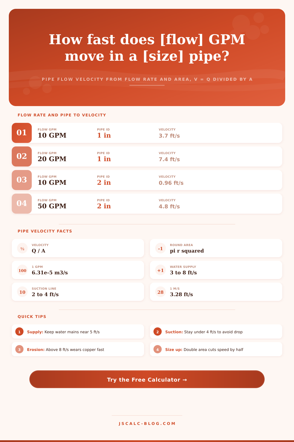
| 1 in | 1.049 | 0.864 | 3.71 ft/s | 18.56 ft/s | Erosion risk |
| 1-1/4 in | 1.380 | 1.496 | 2.15 ft/s | 10.73 ft/s | Above limit |
| 1-1/2 in | 1.610 | 2.036 | 1.58 ft/s | 7.88 ft/s | Near top edge |
| 2 in | 2.067 | 3.356 | 0.96 ft/s | 4.78 ft/s | Good fit |
| 3 in | 3.068 | 7.393 | 0.43 ft/s | 2.17 ft/s | Low, may settle |
| 4 in | 4.026 | 12.730 | 0.25 ft/s | 1.26 ft/s | Oversized here |
| 6 in | 6.065 | 28.890 | 0.11 ft/s | 0.56 ft/s | Very oversized |
⚙Formula Breakdown
💡Pipe Sizing Field Tips
This page’s flow velocity calculator does something that gets asked about every day in HVAC and plumbing design; how fast is the fluid realy flowing through this pipe?
It’s a simple statement of the relationship; it says that flow velocity (v) are equal to the volumetric flow rate (Q) divided by the cross-sectional area of the passage (A). So you feed the thing a pipe size and a flow rate and it gives you actual fluid velocity in both feet per second and meters per second. Then it compares that to recommended velocities for real-world applications. That is when the math are used.
How to Calculate Flow Velocity
Velocity (v) and flow rate (Q), is not interchangeable; people mix up terms, but they’re talking about different things. Flow rate is a volume per unit time, like in gallons per minute or liters per second. On the other hand, velocity is a distance per unit time, like in feet per second. It only depend on the width of pipe. Same 10 gallons per minute pushed through a two-inch line? Pushed through a half-inch line? The velocity go way up since the narrower pipe pushes that same volume through a much smaller opening.
That’s what connects them with cross-section area A: v = Q/A. That’s the difference between how fast it gets there and how much water you have.
The tool divides all of this after converting it into its base SI units so as to keep physics accurate. Cross-section area is converted into square meters; flow rate are normalized to cubic meters per second. About one US gallon per minute converts to 0.00006309 cubic meters per second. Dividing by the area turns velocity into meters per second. Multiplying that by 3.28084 give you the familiar feet per second readout common to most plumbing tables. Normalizing units removes usual source of unit error that sinks most design calculations. No need to remember any conversion factors; just let the process do it for you.
To define the flow area, use geometry dropdown to specify it however fits your situation. For a round pipe, choose by inside diameter, where A = pi times the radius squared. For rectangular duct, choose that option, where A = (internal width) x (height), which is how sheet metal air ducts are actualy sized. If you already know A, just enter it. In each of these cases, the velocity (v) come from the relation v = Q / A, the same equation everywhere.
The reason this flexibility is important: Flows don’t always occur in perfect circles. There’s only one thing that really matters: Nominal pipe labels are just that, nominal. Inside diameter varies by schedule and material. For example, Schedule 40 steel pipe labeled as one inch will have an inner bore nearer to 1.049 inches. Plastic or copper of equal nominal size may vary yet again. Even slight variation in bore will change velocity significant because area increases with the square of diameter. The table below shows reliable bore numbers to use as a starting point for calculation.
The biggest mistake leading to incorrect speed is use of incorrect diameter.
Most designers target about 5 feet per second in their cold water supply and want flow velocity from 3-8 feet per second. They run pump suction lines slower, at maybe 2-4 feet per second (to prevent cavitation and pressure loss). Gravity drains need a minimum of 2 feet per second (or things will settle out). HVAC ducts and compressed air mains runs much faster. If you change the fluid selector on the calculator to oil, air, or water, it changes the suitability band based off that context. It converts a raw number into a design decision.
It’s not only an efficiency issue; velocity drives wear. Anything more than ~8 feet per second becomes audible and starts wearing away at the pipe wall. Copper in particular corrodes even faster above ~10-12 ft/second, with faster erosion corrosion. Doubling the flow area reduce the velocity by about half (a rough estimate). Overspeed runs are often easily remedied by stepping up one nominal pipe size which can of be a very quick fix that earns you quiet operation for years to come… a modest change in material cost.
So when I load the presets, it presents realistic situations: a big main line; a garden hose. How does the same flow rate behave in different size pipes? A two-inch line takes it in stride. Half inch chokes. And it all loads on one screen to make v = Q / A work as a practical sizing tool.
From the design desk to the benchtop, we have a tool that understands physics of flow and area, a tool you can trust. The next time you’re thinking about whether your pipe is too big or too small, remind yourself that velocity is nothing more than volume divided by space. It’s an easy equation with deafening consequences.