EIRP Calculator
Compute Effective Isotropic Radiated Power from transmitter output, antenna gain, cable and connector losses. EIRP equals Tx power plus antenna gain minus feedline loss, reported in dBm and watts, with ERP referenced to a half-wave dipole and the net system gain of your RF chain.
📡Real RF System Presets
🔧RF Chain Inputs
Power at the radio port before the feedline.
Watts are converted with 10 log10(P x 1000).
Peak gain of the antenna in its main lobe.
dBi = dBd + 2.15, converted internally.
Total coax or waveguide loss between radio and antenna.
Insertion loss of each connector or jumper joint.
Count of mated connector pairs in the path.
Shown for context; does not change EIRP math.
Controls rounding on every result card.
🔢Formula Snapshot
📡EIRP From Tx Power and Net Gain
| Tx Power | Net Gain (G - L) | EIRP (dBm) | EIRP (Watts) |
|---|---|---|---|
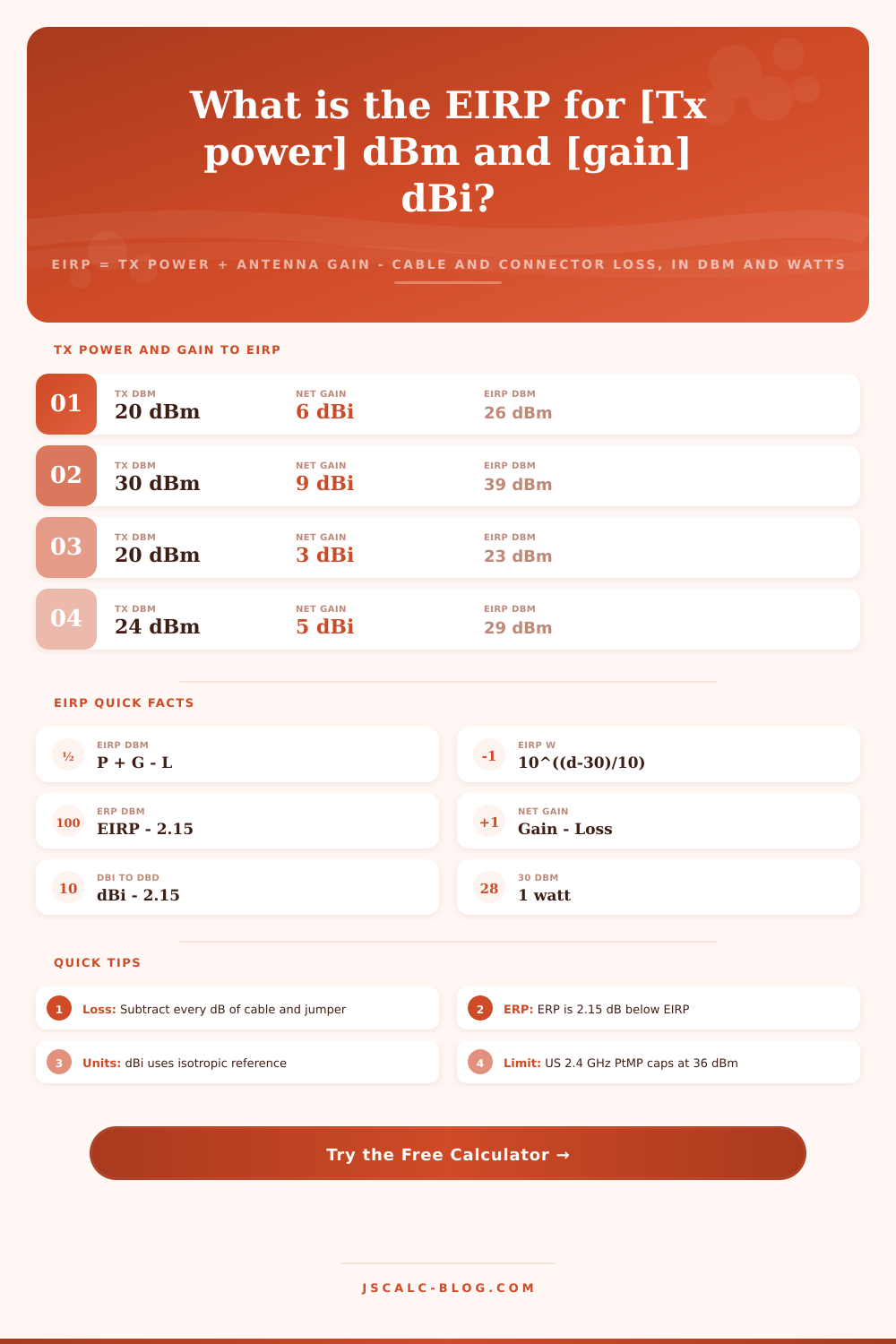
| 20 dBm | 6 dB | 26 dBm | 0.398 W |
| 30 dBm | 9 dB | 39 dBm | 7.94 W |
| 20 dBm | 3 dB | 23 dBm | 0.200 W |
| 24 dBm | 5 dB | 29 dBm | 0.794 W |
| 27 dBm | 12 dB | 39 dBm | 7.94 W |
| 23 dBm | 8 dB | 31 dBm | 1.26 W |
| 33 dBm | 15 dB | 48 dBm | 63.1 W |
| 36 dBm | 6 dB | 42 dBm | 15.8 W |
📏dBm to Watts Reference
| Power (dBm) | Power (Watts) | Power (mW) | Common Use |
|---|---|---|---|
| 0 dBm | 0.001 W | 1 mW | Reference level |
| 10 dBm | 0.01 W | 10 mW | Low-power beacon |
| 20 dBm | 0.1 W | 100 mW | WiFi client radio |
| 23 dBm | 0.2 W | 200 mW | EU 2.4 GHz limit |
| 30 dBm | 1 W | 1000 mW | Max WiFi conducted |
| 36 dBm | 4 W | 4000 mW | US PtMP EIRP cap |
| 43 dBm | 20 W | 20000 mW | Small cell PA |
⚖Regulatory EIRP Limits (Informational)
| Band | Region | Application | EIRP Limit dBm | EIRP Limit W | Note |
|---|---|---|---|---|---|
| 2.4 GHz | US (FCC) | Point-to-multipoint | 36 dBm | 4 W | 30 dBm conducted max |
| 2.4 GHz | EU (ETSI) | WiFi / BLE | 20 dBm | 0.1 W | 100 mW EIRP ceiling |
| 2.4 GHz | US (FCC) | Point-to-point | Up to 158 dBm | Very high | 1 dB PA cut per 3 dBi |
| 5.8 GHz | US (FCC) | PtP UNII-3 | 53 dBm | 200 W | No PA reduction rule |
| 5.15-5.25 GHz | EU (ETSI) | Indoor WiFi | 23 dBm | 0.2 W | 200 mW indoor only |
| 915 MHz | US (FCC) | ISM / LoRa | 36 dBm | 4 W | Part 15.247 spread |
| 868 MHz | EU (ETSI) | ISM / LoRa | 14 dBm | 0.025 W | 25 mW ERP duty cycle |
| 60 GHz | US (FCC) | WiGig / mmWave | 82 dBm | Very high | High-gain arrays |
📡dBi and dBd Gain Conversion
| Antenna Type | Gain (dBi) | Gain (dBd) | Typical Pattern |
|---|---|---|---|
| Isotropic ideal | 0 dBi | -2.15 dBd | Perfect sphere |
| Half-wave dipole | 2.15 dBi | 0 dBd | Omni doughnut |
| Quarter-wave whip | 5.15 dBi | 3 dBd | Vertical omni |
| Collinear omni | 8.15 dBi | 6 dBd | Tall vertical |
| Panel sector | 14 dBi | 11.85 dBd | Directional 90 deg |
| Yagi beam | 16 dBi | 13.85 dBd | Narrow forward |
| Parabolic dish | 30 dBi | 27.85 dBd | Pencil beam |
⚙Formula Breakdown
💡RF Link Planning Tips
You have an antenna specifically designed to take energy from your radio, which outputs exactly one watt, and direct that energy into a narrow beam. The signal should be plenty strong enough to span length of town on paper. But in practice? Most of the power gets absorbed by coaxial cable running up pole. That’s where Effective Isotropic Radiated Power (EIRP) come in.
It’s not just another word to remember. It’s the one and only number that will tell you if your link work or fail. And your neighbor cares about it too, because EIRP is what regulators care about and it tell them the truth about how far your system can reach.
What Is EIRP and Why It Matters
EIRP is an acronym for Effective Isotropic Radiated Power. It’s the amount of power your system would seem to have if it were a perfect point source radiating out of its best direction. That means actual antennas don’t radiate equally in every direction; instead, they concentrate their energy in some sort of beam or doughnut pattern, which causes signal to look stronger then the raw transmitter output indicates.
For example, imagine you have a one watt radio and feed that into a six dBi antenna with no cable loss. Your system would then behave like a four hundred milliwatt source coming from an isotropic source (a perfect point source) at the feed point. Therefore, when it comes to planning for coverage and interfering potential, EIRP is importanter than conducted power.
Decibel math remain easy, it’s addition instead of multiplication. It’s basically Transmit Power + Antenna Gain. Total Feedline Loss. People tend to remember the addition (the gain) and overlook subtraction (loss). That’s where the math becomes expensive.
This page has a calculator that does the math for you right now, but knowing what each number mean helps keep you from shooting yourself in the foot down the road. “Transmitter power” refers to output of your radio port before any cables has been added. Antenna gain should also point to something specific like a reference antenna. Gain is typically specified either as dBd (gain relative to a half-wave dipole) or dBi (gain relative to an isotropic source).
Gain of 8.15 dBi. 6 dBd. It is 12 dBd. The two are not interchangeable; mixing them up gets you a quiet mistake which reduce your range by close to a third. The tool will convert between units internally so you don’t need to do any head-math with specs.
RF links have a quiet killer: feedline loss. As cable lengths increases and frequency increases, so does the attenuation of the cable. At 2.4 GHz, twenty decibels can be eaten by long run of thin RG-58 and you’ve gone from your one watt radio to a few milliwatts before your signal ever reaches antenna.
Upgrade that run to low-loss LMR-400 and you might get back over ten decibels, more than doubling your effective range. Each tenth of a decibel improvement in the feedline is a tenth of a decibel improvement on your final EIRP. Good connectors and short runs pays off directly in radiated power.
That net system gain card in the results tell you just how many decibels of antenna boost remain after subtracting out all those losses. Watts and dBm are regulatory limits and engineering specs that convert back and forth. Rules is usually expressed in watts, but dBm is more convenient for calculating gain and loss. Compliance checking gets easy when you see it in both formats at once.
One other thing: make sure you are comparing apples-to-apples, EIRP vs. ERP. Effective Radiated Power is measured against a half-wave dipole (not an isotropic source). 15 dB less then EIRP. WiFi specs express their limits in terms of EIRP; broadcast and land-mobile rules often gives limits in ERP.
Both are reported on the calculator so you have what you need to comply with whatever standard governs your service, no more guessing about the offset. Realistic presets load parameters for popular systems such as ham repeaters or LoRa sensors. They visualize how antenna gain, feedline losses, and transmitter power trade off by band. You can use them to test out various scenario before committing to hardware.
Confirm results against regulatory reference tables included and tweak power/gain until operating on the correct side of the law for your jurisdiction. If you’re certifying an IoT product or aligning a backhaul dish, the difference between static and a robust connection is getting these numbers right. You should of checked this before.
Begin with the basics, be sure to account for each decibel of loss, and let the apparent power do the talking.