Radio Horizon Distance Calculator
Enter the transmitter and receiver antenna heights to solve the point-to-point radio horizon distance with d = 4.12 times the sum of the square roots of the two heights in meters. Compare the refracted 4/3-earth radio range against the true geometric horizon, in kilometers or miles.
📶Horizon Mode
Radio mode applies atmospheric refraction through the earth curvature factor k. Optical mode is the true line of sight with k = 1.
🏗Real Antenna Presets
📡Link Inputs
Height of the Tx antenna above average terrain.
Unit for the transmitter height above.
Height of the Rx antenna. Set to 0 for a sea-level target.
Unit for the receiver height above.
Refraction factor. 1.333 (4/3) is standard air; 1 is true geometry.
Applies to every result card and the breakdown.
Optional, for context only. Horizon range is frequency independent.
Controls rounding on every result card.
🔢Formula Snapshot
📋Single Antenna Horizon Reference
| Antenna Height | Radio Horizon 4/3 | Optical Horizon | Typical Use |
|---|---|---|---|
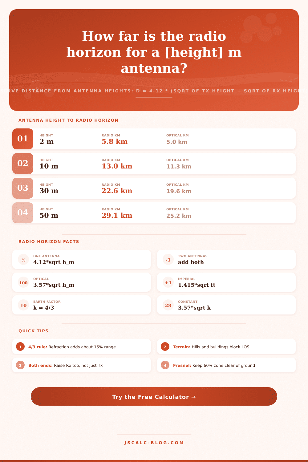
| 2 m | 5.83 km | 5.05 km | Car whip, handheld |
| 10 m | 13.03 km | 11.29 km | House rooftop |
| 30 m | 22.57 km | 19.55 km | Small cell tower |
| 50 m | 29.13 km | 25.24 km | Water tower |
| 100 m | 41.20 km | 35.70 km | Broadcast mast |
| 150 m | 50.46 km | 43.72 km | Tall FM mast |
| 300 m | 71.36 km | 61.83 km | Skyscraper top |
| 553 m | 96.90 km | 83.96 km | CN Tower |
📊Radio vs Geometric Horizon Gain
| Height (m) | Optical (k=1) | Radio (k=4/3) | Extra Range | Percent Gain |
|---|---|---|---|---|
| 5 | 7.98 km | 9.21 km | 1.23 km | +15.4% |
| 20 | 15.97 km | 18.43 km | 2.46 km | +15.4% |
| 50 | 25.24 km | 29.13 km | 3.89 km | +15.4% |
| 100 | 35.70 km | 41.20 km | 5.50 km | +15.4% |
| 250 | 56.45 km | 65.14 km | 8.69 km | +15.4% |
| 500 | 79.83 km | 92.13 km | 12.30 km | +15.4% |
| 1000 | 112.9 km | 130.3 km | 17.4 km | +15.4% |
📏Height Unit Conversions
| Unit | Equals | In Meters | Note |
|---|---|---|---|
| 1 m | 3.281 ft | 1 m | Metric base height |
| 1 ft | 0.3048 m | 0.3048 m | Imperial foot |
| 1 km | 0.6214 mi | 1000 m | Distance output |
| 1 mi | 1.609 km | 1609 m | Statute mile |
| 1 nmi | 1.852 km | 1852 m | Nautical mile |
| 100 ft | 30.48 m | 30.48 m | Tower step |
📡Point-to-Point Link Comparison Grid
| Link Scenario | Tx Height | Rx Height | Tx Horizon | Rx Horizon | Total Radio | Total Optical |
|---|---|---|---|---|---|---|
| Handheld to handheld | 1.5 m | 1.5 m | 5.05 km | 5.05 km | 10.09 km | 8.74 km |
| Car to rooftop | 2 m | 10 m | 5.83 km | 13.03 km | 18.85 km | 16.34 km |
| Rooftop to cell | 10 m | 30 m | 13.03 km | 22.57 km | 35.60 km | 30.84 km |
| Cell to water tower | 30 m | 50 m | 22.57 km | 29.13 km | 51.70 km | 44.79 km |
| FM mast to car | 150 m | 2 m | 50.46 km | 5.83 km | 56.28 km | 48.76 km |
| Tower to tower | 100 m | 100 m | 41.20 km | 41.20 km | 82.40 km | 71.39 km |
| Ship to ship radar | 20 m | 20 m | 18.43 km | 18.43 km | 36.85 km | 31.93 km |
| Drone to ground | 120 m | 2 m | 45.13 km | 5.83 km | 50.95 km | 44.14 km |
| Aircraft to ground | 10000 m | 10 m | 412.0 km | 13.03 km | 425.0 km | 368.2 km |
| Mountain to valley | 1500 m | 5 m | 159.6 km | 9.21 km | 168.8 km | 146.2 km |
⚙Formula Breakdown
💡Practical Range Tips
What is the radio horizon distance? How far will a signal travel before being blocked by the curvature of the earth? This is useful for planning wireless networks or installing antenna.
Radio horizon range are set almost entirely by antenna height, not by transmitter power or frequency. Given the height of your transmitting antenna and the height of your receiving antenna, this tool return the total point-to-point line of sight distance. And it compares that refracted radio number with true geometric horizon so you know exactly how much atmosphere is helping your particular link.
How to Calculate Radio Horizon Distance
This means that when you’re close to the ground, the radio wave travels in a straight line, but the earth under it curve downward. At some point, the surface falls below the beam and there’s no longer any direct signal. The further out that tangent point lie, the higher your antenna is. And here’s the kicker: because the horizon distance of a single antenna is proportional to the square root of its height, you get diminishing returns as you go higher. That fourfold increase in height (ten to forty meters) only double the horizon.
It’s for this reason that broadcasters goes chasing after mountaintops and other tall towers. They can’t buy themselves additional distance by simply pumping up the wattage; that’s what height would of already given them.
The radio horizon (in kilometers) for a single antenna is equal to 4.12 times the square root of its height in meters under normal atmospheric conditions. The geometric, or optical, horizon employ a lower constant that assumes no atmospheric bending. That is how refraction works.
On a point-to-point link, each antenna contribute to range. So combined radio horizon equals the sum of transmitter and receiver individual horizons. The calculator take all three into account at the same time. It displays the substituted values in its breakdown panel where you can check the math by hand or copy it into your report.
But radio waves don’t go exactly straight up in the air; they bend a little bit from effect of the air. The air gets less thick higher up. This bends waves slightly outward toward you at ground. It also curves the waves a tiny bit around the globe. To make things easier to model, engineers pretend that the earth has 4/3 of its actual radius; this is called the 4/3 earth model. This makes the horizon stay at a constant value of 4.12 rather than its actual geometric value. That’s about a fifteen percent improvement in range for free.
If you want to model something other than usual condition… Maybe some really dry air or ducting, you can also just plug in whatever earth curvature factor you like and the tool will model it accordingly.
You input the height of the transmitter (and feet/meters), then also the receiver antenna height. Next, you set the earth factor. This is set to 1.333 by default for normal air and you can change it if need be. Then select miles/kilometers as output format. Click calculate and it displays a set of four cards with results.
The first card is overall radio horizon, i.e., the headline distance from one station to another. Cards two and three break out individual horizons for each antenna. That way, if one end is fixed and you’re trying to decide how high to put up the other, this is helpful. Card four displays the geometric horizon at the same antenna heights. So you can see just how much refraction might contribute on any particular path.
Now imagine you have a 30 meter tall tower, and it talks to a 2 meter long mobile whip. What’s your transmitter horizon? It is about 22.6 kilometers. What’s your receiver horizon? It is roughly 5.8 kilometers. Add them up, and that gives you a total radio horizon of 28.4 kilometers. If we use geometry, we come out at about 24.6 kilometers. So refraction is buying you almost four extra kilometers. The status line sums all this up in plain language.
That’s what folks get wrong: They remember that raising the receiving end helps. It does. But they forget that both ends matter so if you raise both then you get even better results.
They’re loaded with heights gathered from routine radio work. A car whip connects you to a rooftop, which links to a cell tower. A hand-held radio works from one person to another, just enough over the horizon for two people with radios held at head height. An FM mast and a CN Tower show how broadcast structures extend the horizon to fifty and then ninety kilometers out. There are ship radar and drone presets, and even a 10,000 meter aircraft preset whose horizon extends to more than four hundred kilometers. Each loads in seconds, filling the form and calculating on the fly so you can have an instant sense of how far your reach will be depending on how high it might be.
Real terrain doesn’t usually cooperate. A link can be blocked by hills, buildings, or even trees well short of theoretical horizon. For a good connection, you also want to keep about sixty percent of the first Fresnel zone clear, not just the direct ray. Conversely, in warm humid weather, where atmospheric ducting occurs, UHF and VHF signals can travel much farther then the 4/3 prediction.
Think of the radio horizon as an upper bound on reliable line of sight service. That’s useful because it lets you get quick and defensible distance figures when planning out links, and it tells you how far your signal will go based off its height.