Compressed Air Pressure Drop Calculator
Size rigid shop and plant distribution piping for a given SCFM, run length, and line pressure using the Harris compressed-air formula, then see the estimated pressure drop, delivered pressure, and the smallest pipe that stays under your target.
🎯Real Piping Presets
🔧Piping Inputs
Standard cubic feet per minute of free air the run must carry.
Auto-filled from the dropdown; override for copper, PEX, or Sch 80.
Elbows, tees, and valves add feet. Use the helper below.
Many shops aim for 2 to 3 psi, or about 10% of line pressure.
The fittings helper multiplies counts by typical equivalent-length factors and writes the total into the fittings field above. Edit that field directly to override.
🔢Formula Snapshot
📏Schedule 40 Steel Inside Diameters
| Nominal Size | Actual ID (in) | ID (mm) | Typical Use |
|---|---|---|---|
| 1/2 in | 0.622 | 15.8 | Single tool drop, short |
| 3/4 in | 0.824 | 20.9 | Bench drop, small shop |
| 1 in | 1.049 | 26.6 | Branch line, mid shop |
| 1-1/4 in | 1.380 | 35.1 | Sub-header, CNC feed |
| 1-1/2 in | 1.610 | 40.9 | Header, busy shop |
| 2 in | 2.067 | 52.5 | Main header, small plant |
| 2-1/2 in | 2.469 | 62.7 | Plant main, high flow |
| 3 in | 3.068 | 77.9 | Large plant ring main |
📊Pipe Size vs Drop Comparison Grid
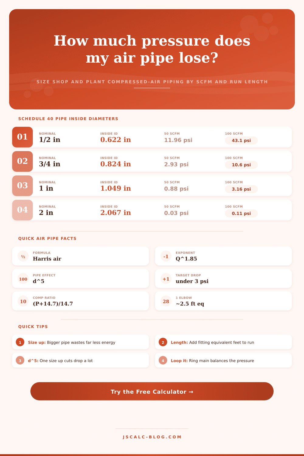
Estimated pressure drop (psi) over a 100 ft run at 100 psi line pressure, for three common flow rates. Notice how one nominal size larger slashes the drop because of the d⁵ term.
| Nominal Size | ID (in) | 25 SCFM | 50 SCFM | 100 SCFM | Verdict at 50 SCFM |
|---|---|---|---|---|---|
| 1/2 in | 0.622 | 3.32 | 11.96 | 43.12 | Far too small |
| 3/4 in | 0.824 | 0.81 | 2.93 | 10.57 | Short drops only |
| 1 in | 1.049 | 0.24 | 0.88 | 3.16 | Good branch line |
| 1-1/4 in | 1.380 | 0.06 | 0.22 | 0.80 | Roomy sub-header |
| 1-1/2 in | 1.610 | 0.03 | 0.10 | 0.37 | Generous header |
| 2 in | 2.067 | 0.01 | 0.03 | 0.11 | Main header |
| 2-1/2 in | 2.469 | 0.00 | 0.01 | 0.04 | Oversized here |
| 3 in | 3.068 | 0.00 | 0.00 | 0.01 | Plant ring main |
📐Recommended Size by Flow and Length
Smallest Schedule 40 size that typically holds the drop under about 3 psi at 100 psi line pressure. Add fitting equivalent length before comparing.
| Flow (SCFM) | 50 ft run | 100 ft run | 200 ft run | 400 ft run |
|---|---|---|---|---|
| 10 SCFM | 1/2 in | 1/2 in | 3/4 in | 3/4 in |
| 25 SCFM | 3/4 in | 3/4 in | 1 in | 1 in |
| 50 SCFM | 3/4 in | 1 in | 1 in | 1-1/4 in |
| 100 SCFM | 1 in | 1-1/4 in | 1-1/4 in | 1-1/2 in |
| 150 SCFM | 1-1/4 in | 1-1/4 in | 1-1/2 in | 2 in |
| 250 SCFM | 1-1/2 in | 1-1/2 in | 2 in | 2 in |
| 400 SCFM | 2 in | 2 in | 2 in | 2-1/2 in |
| 600 SCFM | 2 in | 2 in | 2-1/2 in | 3 in |
🔩Fitting Equivalent Lengths
Approximate straight-pipe feet each fitting adds. Values scale with pipe size; these are mid-range figures for 1 in to 2 in steel pipe.
| Fitting Type | Equivalent Feet | Notes |
|---|---|---|
| 90° standard elbow | ~2.5 ft | Long-radius elbows add less |
| 45° elbow | ~1.3 ft | Gentler turn, lower loss |
| Tee, straight run | ~2.0 ft | Flow passes through |
| Tee, branch flow | ~5.0 ft | Flow turns into branch |
| Gate or ball valve (open) | ~1.0 ft | Full-bore, low loss |
| Globe or angle valve | ~30 ft | High loss, avoid on mains |
| Swing check valve | ~8 ft | Depends on disc design |
| Sudden coupling/union | ~0.5 ft | Minor, count on long runs |
⚙Full Formula Breakdown
💡Practical Sizing Tips
The tool isn’t always at fault. More often then not, the problem is an air line that is too long or a pipe with to small a diameter. This starves equipment of enough compressed air to work effectivey.
Compressed air sounds easy until you attempt to move it across shop floor while retaining half the pressure. Usually, the secret to making slow impact wrench spin quickly isn’t horsepower but hydraulic math. As you go down that line, air expands as pressure decreases, which change its behavior, it’s physics, and it doesn’t forgive. Standard formulas aren’t up to task. To get around this, engineers use empirical charts based off years of testing. The calculator above use the Harris formula, which accounts for shifting density as the air travels along and handles heavy lifting.
How to Fix Compressed Air Problems
Don’t worry about remembering coefficients. Do be concerned with understanding what they represent. Because resistance increase as demand grows, flow rate has a huge impact. Doubling your airflow won’t double the pressure drop. Instead, it will multiply it by a factor that gets closer to four. And that’s the exponential relationship that makes it possible for a modest increase in tool usage to cause chaos on an undersized system overnight.
Pipe diameter is the great equalizer Friction loss is related to the fifth power of pipe diameter, so bigger pipes has the numbers in their favor. While you’ll pay a bit extra initially (both materials and install), the payoff is slashing resistance by a factor of 30 or more. A few bucks today = endless energy savings.
When designing air systems, most shops will target keeping total pressure drop at less than three psi between compressor outlet and the farthest tool. Beyond that, you begin losing money from your operating margin due to wasted energy and slower cycle times on pneumatic machine.
Where many folks trip themselves up is length, simply measuring straight pipe. It’s easy to overlook all elbows, tees, valves, filters… which all add equivalent length to the run. For example: one globe valve can be as restrictive as thirty feet of straight pipe internally! This is how we calculate fittings. This allows you to tally them with total run length for a more realistic estimate based on real world conditions rather than an idealized straight line. When your tools is starving, this is when you need them the most, on a busy production day. You’ll gloss right over those losses if you don’t take them into account.
Another consideration is condensate management. All that water in the lines causes not only corrosion issues but other blockages too that slowy constrict flow over time. Slightly sloping branch line help drain moisture away from critical points before it becomes a problem.
Internal roughness is determined by material choice, and I will talk more about that later. They use steel a lot (cheap and durable), but sometimes they’ll go with copper or aluminum to get smoother interiors. For now, assume a steel interior, unless specified otherwise. That’s why we’ve got baseline inside diameters from the reference tables, for Schedule 40 steel, which is the industry workhorse. Adjusting actual internal diameter in the custom field will ensure the math stays true whether you’re piping water, gas, or something else like PEX. Different schedule?) through your walls.
When sizing out a system, don’t expect to hit an exact number. It’s a trade-off between operational efficiency and capital cost. The more efficient a system is at balancing pressure, the less likely it is to have one person always getting short straw, aka the last tool to get air. Ring main layouts often achieve this effect by feeding drops from two sides, essentially cutting the air delivery distance in half to all outlets. If you plan ahead by sizing your main lines generously, you will get more reliable results.
Inputting your actual lengths and flows into the calculator above will run the math for you. That way there are no guessing games or frustrated workers. This is the bottom line. Good air system design just doesn’t show itself. If it’s working, no one sees it. But if it ain’t, we all complain about it.
Calculating pressure drop takes time, but it guarantees your tools gets the consistent force they was designed for. It’s a little bit of upfront planning that saves costly downtime down the road. Size your lines right and keep them clear. Your shop will run smoother then you think.