Cable Bend Radius Calculator
Find the minimum cable bend radius from minimum radius = multiplier times outer diameter. Compare the static installed limit with the larger dynamic during-pull limit, get the service loop diameter, and check whether a proposed bend radius passes or fails for your cable type.
🔗Real Cable Presets
🔧Cable and Bend Inputs
Sets the default static and dynamic multipliers.
Dynamic uses the larger during-pull multiplier.
Overall jacket diameter of the finished cable.
Results are shown in both mm and inches.
Enter a value to force k; 0 uses the table default.
Informational; large bundles favor the higher limit.
Armor adds 4x to the static multiplier.
In the OD unit above; leave 0 to skip pass/fail.
🔢Formula Snapshot
📋Bend Radius by Cable Type
| Cable Type | Static Multiplier | Dynamic Multiplier | Common Rule |
|---|---|---|---|
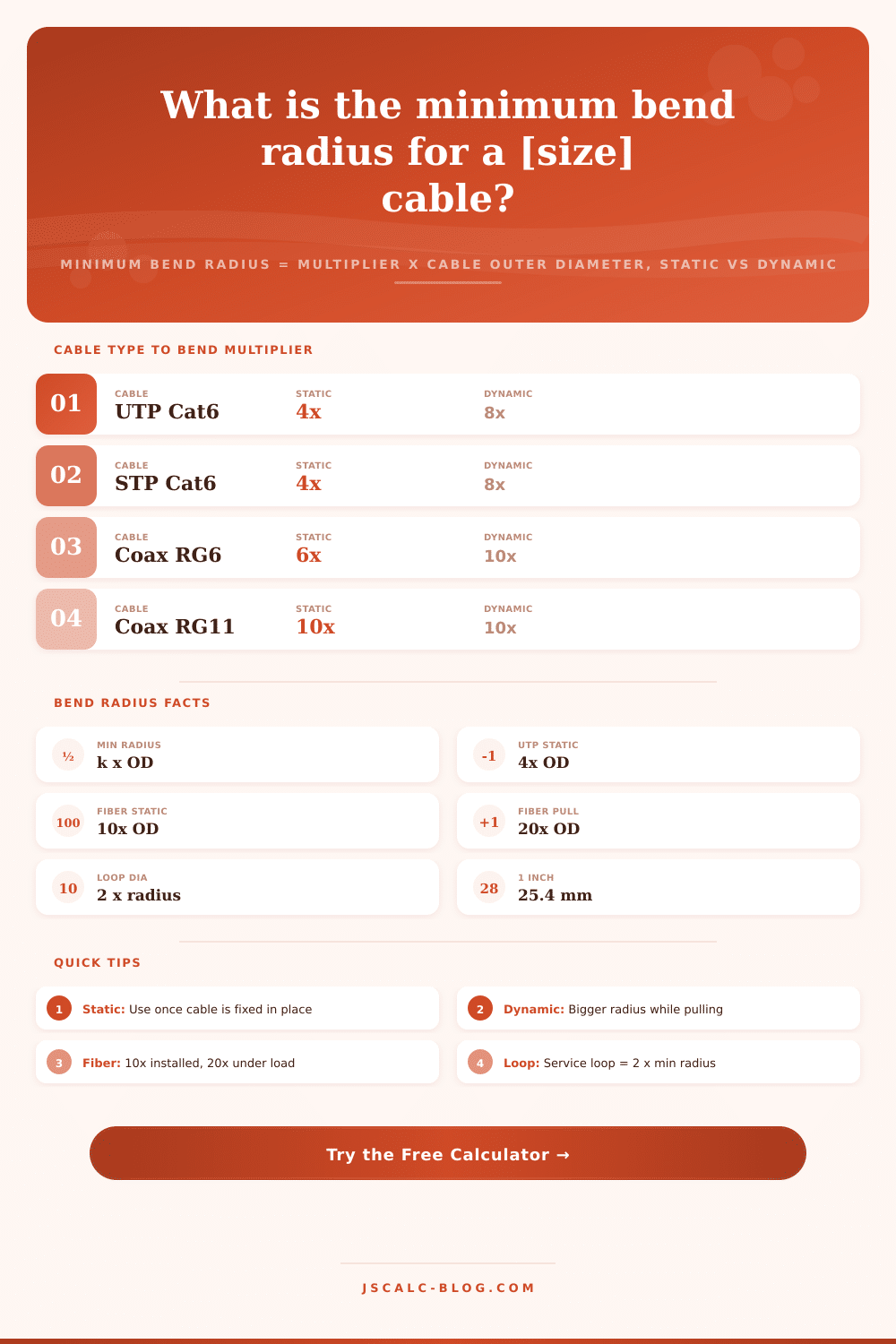
| UTP Ethernet (Cat5e/6) | 4x OD | 8x OD | TIA 4x horizontal |
| STP shielded twisted pair | 4x OD | 8x OD | 8x when armored |
| Coax RG6 / RG59 | 6x OD | 10x OD | Maker 4x to 6x |
| Coax RG11 / hardline | 10x OD | 10x OD | Stiff, fixed limit |
| Fiber single-mode | 10x OD | 20x OD | 20x under load |
| Fiber multimode / trunk | 10x OD | 20x OD | 20x during pull |
| Power cable unshielded | 8x OD | 12x OD | NEC 8x typical |
| Power shielded / armored | 12x OD | 12x OD | 12x for shield |
📏Cat6 UTP OD to Minimum Radius
| Outer Diameter | Static 4x Radius | Dynamic 8x Radius | Loop Diameter (2 x 4x) |
|---|---|---|---|
| 5 mm | 20 mm | 40 mm | 40 mm |
| 5.5 mm | 22 mm | 44 mm | 44 mm |
| 6 mm | 24 mm | 48 mm | 48 mm |
| 6.5 mm | 26 mm | 52 mm | 52 mm |
| 7 mm | 28 mm | 56 mm | 56 mm |
| 7.5 mm | 30 mm | 60 mm | 60 mm |
| 8 mm | 32 mm | 64 mm | 64 mm |
| 9 mm | 36 mm | 72 mm | 72 mm |
📐Millimeter and Inch Conversions
| Value | Equals | In Millimeters | Note |
|---|---|---|---|
| 1 in | 25.4 mm | 25.4 mm | One inch of OD |
| 0.25 in | 6.35 mm | 6.35 mm | Typical Cat6 OD |
| 1 mm | 0.0394 in | 1 mm | Metric jacket |
| 10 mm | 0.394 in | 10 mm | Thick power cable |
| 1 ft | 304.8 mm | 304.8 mm | Service loop scale |
| 1 cm | 10 mm | 10 mm | Centimeter |
🗃Static vs Dynamic Comparison Grid
| Cable Type | Static Multiplier | Dynamic Multiplier | Typical OD | Min Static Radius | Min Loop Diameter |
|---|---|---|---|---|---|
| UTP Cat6 | 4x | 8x | 6 mm | 24 mm | 48 mm |
| STP Cat6a | 4x | 8x | 7.5 mm | 30 mm | 60 mm |
| Coax RG6 | 6x | 10x | 6.9 mm | 41 mm | 82 mm |
| Coax RG11 | 10x | 10x | 10.3 mm | 103 mm | 206 mm |
| Fiber single-mode | 10x | 20x | 3 mm | 30 mm | 60 mm |
| Fiber 12-strand trunk | 10x | 20x | 8 mm | 80 mm | 160 mm |
| Power unshielded | 8x | 12x | 15 mm | 120 mm | 240 mm |
| Power armored 3-core | 12x | 12x | 25 mm | 300 mm | 600 mm |
| Control cable | 6x | 12x | 8 mm | 48 mm | 96 mm |
| Speaker low voltage | 5x | 10x | 8 mm | 40 mm | 80 mm |
⚙Formula Breakdown
💡Bend Radius Field Tips
When coiling the cable around the back of a rack or running it into a corner, you’re frequently working with tight areas. Sometimes it looks good at the time, but then you notice some sort of signal loss or physical damage occurs later. A cable’s minimum bend radius are the difference between success and failure in an install. And many techs makes this rule-of-thumb an afterthought.
That’s why we built our calculator (above) to do the math for you. With one simple set of inputs, it delivers instant solutions for changing pull conditions and static installed limits. You won’t have to dig through a half-dozen different datasheets. It translates complex engineering rules into real-world measurements you can apply onsite.
Why Minimum Bend Radius Matters for Cables
There’s a limit to how small a turn will be for any given cable. Twisted pair Ethernet untwist if you bend it too much. Return loss goes up. Crosstalk increase. Channel certification fails. Coax kink if bent too tight, shifting its impedance. Reflected signal mess up data or video signals. Even fiber is sensitive to tight turns. Macrobends let light leak out of the core. Over time, bending glass may cracks. Power cables experience mechanical strain at their insulating layer.
It’s pretty easy to recall the rule: Minimum radius = some number x outer diameter of cable. All you have to do is know what number to multiply by for each type of cable. This confuses static and dynamic limits. A cable that is fixed in place but not under any tension are static. A cable being pulled is dynamic. You also must take into account that pulling puts stress on the conductors and the jacket due to friction and tension.
When in place, a typical Cat6 cable can withstand four times the diameter without issue. But when bent that tight while being pulled through conduit, you may damage the pairs inside. Typically, the dynamic limit of a twisted pair is double its static limit (eight times versus four). For fiber, it’s 20 times the diameter when installing versus 10 times after settling in. So people pull using the static number and fail. They think the installed number are a general constant. But it isn’t. It’s a state dependent threshold.
It will automatically do lookups and conversions. You can see what goes in and check that what comes out of it makes sense. The outer diameter is the total jacket size which includes all other sizes, not only conductor width. If it’s an armored cable or has a metal shield, it’ll be stiffer. They might need a bigger radius to avoid crushing any internals or cracking the armor. Flagging them as armored jackets tells the calculator to increase the multiplier to account for this.
Likewise, maybe your manufacturer’s spec sheet says to go stricter on tolerances different than what industry average provides. You can override the default multipliers to make sure the number matches your materials instead of some generic average. The math keeps it from causing issues with slack and service loops.
What we need for a service loop isn’t just a radius but a diameter. Why? Because double the radius equals the diameter. This means you need at least a sixty millimeter coil. The cable must be designed for a minimum thirty millimeter radius if you want some room to play in that loop. Otherwise, you get stress points or microbends which will ruin performance after all those years of being expanded and contracted by heat.
This way, the calculator tells you what diameter loop you’ll need and helps you plan out your slack storage in junction boxes or patch panels. It even helps with sag clearance. How deep should I leave it when it comes through a faceplate to make that nice ninety degree turn around?
No matter what size cable you are using, it’s not uncommon for job site teams to work together with mixed units. While conduit charts reference millimeters, datasheets will quote inches. An inch is precisely twenty-five-point-four millimeters. Trying to remember that conversion while you’re out there bending cables will hurt your concentration. With both outputs displayed at once, however, you can visually compare what you’ve got available against what you need.
Plan your pull path across a ceiling grid or check that proposed wall box bend. Know ahead of time if your minimum radius test passes or fails, have confidence when you go to commit to the install. Keep the signal strong and keep the cabling clean. That means respecting that curve, and protecting the soundness of everything from high speed fiber trunks to low voltage audio feeds. As long as the building lives, so does the link.