Coaxial Cable Loss Calculator
Estimate total RF loss through a coax feedline from cable type, frequency, and run length, then add connector loss and VSWR mismatch loss. See total attenuation in dB, power delivered to the antenna, the effective radiated fraction, and loss per 100 ft at your frequency for RG58, RG59, RG6, RG213, and LMR series cable.
📡Real Coax Feedline Presets
🔧Feedline Inputs
Impedance and loss table are set from the cable choice.
Loss scales with the square root of frequency.
One way length from radio to antenna.
Meters convert to feet at 3.281 ft per meter.
Power entering the feedline at the radio.
Choose watts or dBm for the input level.
Count each connector pair along the run.
Typical PL259 or N is 0.1 to 0.5 dB each.
1.0 is a perfect match; adds mismatch loss above 1.
Controls rounding on every result card.
🔢Formula Snapshot
📋Matched Loss per 100 ft by Cable
| Coax Type | Impedance | 100 MHz | 450 MHz | 900 MHz | 2400 MHz |
|---|---|---|---|---|---|
| RG174 | 50 ohm | 8.8 dB | 19.0 dB | 27.9 dB | 47.0 dB |
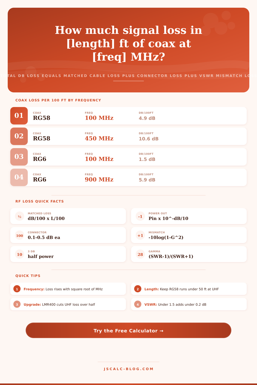
| RG58 | 50 ohm | 4.9 dB | 10.6 dB | 15.6 dB | 26.2 dB |
| RG59 | 75 ohm | 3.4 dB | 7.3 dB | 10.8 dB | 18.1 dB |
| RG6 | 75 ohm | 1.9 dB | 4.3 dB | 5.9 dB | 9.8 dB |
| RG8 | 50 ohm | 1.8 dB | 3.9 dB | 5.7 dB | 9.6 dB |
| RG213 | 50 ohm | 1.9 dB | 4.2 dB | 6.2 dB | 10.4 dB |
| LMR240 | 50 ohm | 2.2 dB | 4.8 dB | 6.9 dB | 11.6 dB |
| LMR400 | 50 ohm | 1.5 dB | 2.7 dB | 3.9 dB | 6.8 dB |
| LMR600 | 50 ohm | 0.9 dB | 1.8 dB | 2.5 dB | 4.4 dB |
📡Common Coax by Application and Band
| Cable | Impedance | Typical Use | Best Band | Note |
|---|---|---|---|---|
| RG174 | 50 ohm | GPS, jumpers | Short runs | Very lossy, keep short |
| RG58 | 50 ohm | CB, mobile | HF to VHF | Flexible thin coax |
| RG59 | 75 ohm | CCTV, video | VHF baseband | Legacy 75 ohm line |
| RG6 | 75 ohm | TV, satellite | UHF to SHF | Low loss for 75 ohm |
| RG8 | 50 ohm | Ham base | HF to VHF | Thick low loss coax |
| RG213 | 50 ohm | Ham, base | HF to UHF | Rugged double shield |
| LMR240 | 50 ohm | Mobile, WiFi | VHF to UHF | RG8X class upgrade |
| LMR400 | 50 ohm | WiFi, repeater | UHF to SHF | Low loss workhorse |
| LMR600 | 50 ohm | Long tower runs | UHF to SHF | Lowest loss, stiff |
📊VSWR to Mismatch Loss
| VSWR | Reflection Γ | Reflected Power | Mismatch Loss | Rating |
|---|---|---|---|---|
| 1.0 : 1 | 0.000 | 0.0 % | 0.00 dB | Perfect |
| 1.2 : 1 | 0.091 | 0.8 % | 0.04 dB | Excellent |
| 1.5 : 1 | 0.200 | 4.0 % | 0.18 dB | Good |
| 2.0 : 1 | 0.333 | 11.1 % | 0.51 dB | Acceptable |
| 2.5 : 1 | 0.429 | 18.4 % | 0.88 dB | Marginal |
| 3.0 : 1 | 0.500 | 25.0 % | 1.25 dB | Poor |
| 4.0 : 1 | 0.600 | 36.0 % | 1.94 dB | Bad |
| 5.0 : 1 | 0.667 | 44.4 % | 2.55 dB | Very poor |
📏Decibel Loss to Power Remaining
| Total Loss | Power Remaining | Power Lost | 100 W In Gives | Note |
|---|---|---|---|---|
| 0.5 dB | 89.1 % | 10.9 % | 89.1 W | Barely noticed |
| 1 dB | 79.4 % | 20.6 % | 79.4 W | Minor loss |
| 2 dB | 63.1 % | 36.9 % | 63.1 W | Noticeable |
| 3 dB | 50.1 % | 49.9 % | 50.1 W | Half power |
| 6 dB | 25.1 % | 74.9 % | 25.1 W | Quarter power |
| 10 dB | 10.0 % | 90.0 % | 10.0 W | One tenth left |
| 20 dB | 1.0 % | 99.0 % | 1.0 W | Severe loss |
⚙Formula Breakdown
💡Coax Feedline Tips
What good is having an antenna tuned for best gain if you strangle the signal as soon as it gets out of your radio? Cable is what diminishes the signal. The antenna does its job; the cable weaken it. Coaxial cable turns the transmitter’s power into heat with every foot of length. The longer the cable, the more loss; the higher the frequency, the greater the loss. Your investment in coaxial cable result in no range at all so you’re simply paying for something you’ll never get.
Enter your run length, frequency, and cable type into calculator on this page and let numbers do the talking. Time to ditch the long RG58 drop? Upgrade to some beefier cable? Never trust coax to be totaly see-through. There’s still resistance in the center conductor. There’s also still something called dielectric absorbing some of the energy. And both degrade as frequency increases due to skin effect which causes current to crowd toward outside of the conductor. That makes for increased effective resistance proportional to square root of frequency. What works fine on HF might be wasting most of your signal at UHF frequencies. For example, a thin run of RG58 will lose roughly 5 dB/100 feet at 100 MHz increasing to more than 10 dB/100 feet by 450 MHz. Ten decibels equals one tenth of your power getting through. Ouch! It is a brutal signal-loss tax.
How to Stop Losing Radio Signal in Your Cable
Matched loss is the core of the calculation. Matched loss = (loss/100 x run length)/100 That means take your loss per 100 feet times your run length and divide by 100. Then the tool will look up reference losses for each type of cable at various frequencies. It will then scale those values to match your actual frequency based off that square root relationship. So if you have the loss at 450 MHz, the loss at 900 MHz would of been approximately the 450 MHz value times the square root of two. This method means you don’t need separate tables for each band and the number stays fairly realistic across the HF, VHF, UHF, and microwave bands. It is just a simple application of physics to what you are working with.
The right type of cable makes a huge difference in performance. Video systems requires 75-ohm cables (like RG6), whereas radio stuff works best on 50-ohm ones like LMR400 or RG8. That’s because you want all three parts, antenna, cable and radio. To match impedances so reflections aren’t a problem. But even then, you have normal dielectric and conductor losses on your line. Connector pairs adds some insertion loss (usually.1 to.5 dB each, depending on how they’re installed and what family). This isn’t anything for short runs but for long runs with multiple connectors, it can equal a couple feet of loss. Don’t ignore ’em, just count ’em.
An antenna impedance mismatch happen when an antenna doesn’t match the feedline, reflecting some power back toward the transmitter. How much power does it reflect? The voltage standing wave ratio determines that. For instance, a 1.5 to 1 match results in just 4 percent reflected power and less than 0.2 dB of mismatch loss (trivial). On the other hand, a 3 to 1 match reflects a full quarter of all power and more than 1 dB of loss (that’s what people get wrong). They think the cable is bad but the true culprit is a poorly tuned antenna. The calculator puts this mismatch loss into the total so you can see actual picture from end-to-end.
The instant you read the result cards, you know exactly what’s going on. Total loss sums mismatch, connector, and matched losses into one decibel figure. That loss as a wattage value comes from power to antenna. Then you see the fraction (often the most surprising) of power that survives the trip. You get loss per 100 feet at your specific operating frequency so you can compare cable types before buying. You also gets attenuation that matches your specific operating frequency.
These are real world examples. Pre-sets load with real-world situations you can fiddle with or learn from. There are WiFi runs on LMR400, CB runs on RG58, tower drops on LMR600. They is all filled out for you to show the power delivered depending on the cable selected. Then tweak one value and see what happens if you upgrade from thin coax to lower loss options.
Match the cable grade to the run length and band to minimize loss. You may be surprised at how much power you can save by upgrading from RG58 to LMR400 when feeding a UHF run longer than 50 feet. If your signal isn’t hitting the sky, it’s heating the feedline. Learn to tune your antenna before judging your feedline.