Cable Attenuation Calculator
Estimate signal loss over a cable run in decibels, then convert to output power and percent power remaining. Loss scales with length, rises with the square root of frequency from skin effect, and gains a small correction for hot cable, so you can size any twisted pair or coax link with confidence.
🎯Real Cable Run Presets
📡Cable and Signal Inputs
Sets the reference dB/100m and reference frequency.
Rated loss at the reference frequency below.
Frequency at which the spec above is quoted.
Actual signal frequency on the run.
Total physical run length of the cable.
Feet are converted at 3.2808 ft per meter.
Transmit level at the near end, 0 dBm = 1 mW.
Copper loss rises about 0.2 percent per C above 20.
Controls rounding on every result card.
🔢Formula Snapshot
📋Decibel Loss to Percent Power
| Loss (dB) | Power Remaining | Power Lost | Reads As |
|---|---|---|---|
| 0 dB | 100 % | 0 % | No loss |
| 1 dB | 79.4 % | 20.6 % | Barely felt |
| 3 dB | 50.1 % | 49.9 % | Half power |
| 6 dB | 25.1 % | 74.9 % | Quarter power |
| 10 dB | 10.0 % | 90.0 % | One tenth |
| 13 dB | 5.0 % | 95.0 % | One twentieth |
| 20 dB | 1.0 % | 99.0 % | One hundredth |
| 30 dB | 0.1 % | 99.9 % | One thousandth |
📡Cable Attenuation Comparison Grid
| Cable | 10 MHz | 100 MHz | 250 MHz | 500 MHz | 1000 MHz | 2400 MHz |
|---|---|---|---|---|---|---|
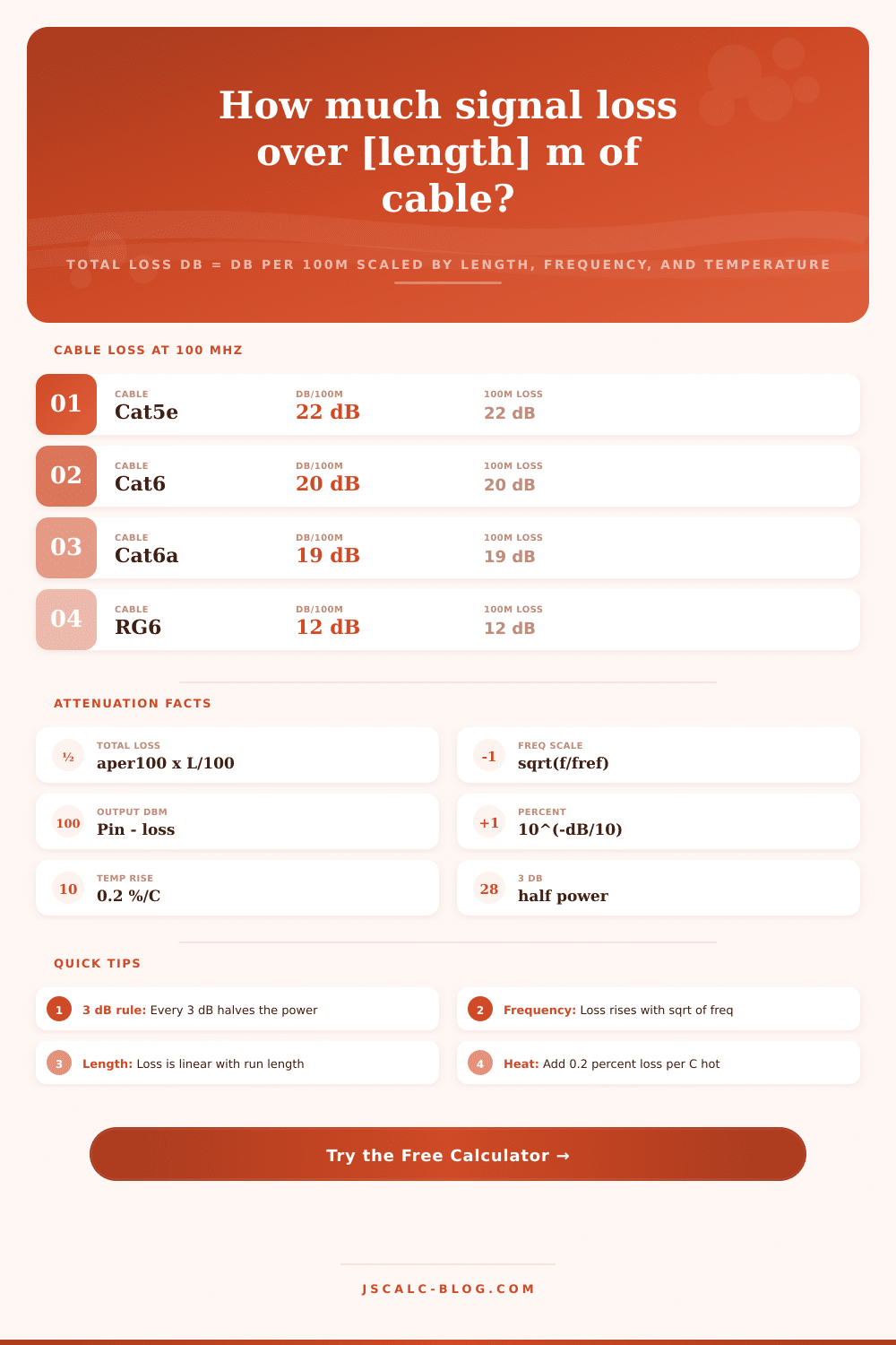
| Cat5e | 6.5 | 22 | 36 | 52 | 75 | 118 |
| Cat6 | 5.9 | 20 | 32 | 46 | 66 | 105 |
| Cat6a | 5.6 | 19 | 30 | 43 | 61 | 96 |
| RG6 coax | 3.8 | 12 | 19 | 28 | 41 | 66 |
| RG59 coax | 4.7 | 15 | 24 | 35 | 51 | 82 |
| RG58 coax | 5.1 | 16 | 26 | 38 | 55 | 88 |
| RG174 thin | 10.1 | 32 | 51 | 73 | 105 | 168 |
| RG213 coax | 2.5 | 8 | 13 | 19 | 28 | 45 |
| LMR240 | 2.2 | 7 | 11 | 16 | 24 | 38 |
| LMR400 | 1.3 | 4 | 6.5 | 9.5 | 14 | 22 |
📏Length and Unit Conversions
| Length | Equals | In Meters | Note |
|---|---|---|---|
| 1 m | 3.2808 ft | 1 m | Metric base |
| 1 ft | 0.3048 m | 0.3048 m | Imperial foot |
| 100 m | 328.08 ft | 100 m | Spec length |
| 100 ft | 30.48 m | 30.48 m | US spec run |
| 1 MHz | 0.001 GHz | - | Megahertz |
| 1 GHz | 1000 MHz | - | Gigahertz |
⚙Formula Breakdown
💡Cable Loss Field Tips
If your cable sucks, you might have dead spots even with an expensive router. Sure, your router has all the bells and whistles, but the cable is what’s failing. As the signal travels down this copper line, some of its energy becomes heat (attenuation). That’s why it’s not either works or doesn’t work. It’s how much it’s degraded, which are a function of both distance and frequency, as well as outside weather conditions.
The calculator do all that math for you so you don’t need to derive the number. You just need to make a choice. But first, let’s talk about decibels.
Why Your Cable Matters for Good WiFi
Decibels is a log unit (logarithmic scale), which sounds like abstract math but becomes clear when you see what happens to your signal as it vanishes. For every 3dB of loss, you lose half of your signal. For every 6dB of loss, it are down to a quarter of its former self. If you lose 10dB, just one-tenth of your signal make it through. These can add up fast, and most folks greatly underestimate that.
Because it shows both values, decibels and percentage, you understand much faster when half of something goes away (fifty percent) instead of trying to visualize that number (three dB) on some spec sheet. That’s what fills the gap between geeky specs and real-world performance.
The initial variable to consider is length. When looking at different cables, they is rated based off how many db’s are lost per 100 meters. Sounds reasonable, right? Right up until you have more than 100m of line. Twenty db lost in 100 is fine but now that goes to 40db if you have 200, and it go up from there. It’s a linear and merciless equation.
Can I say that in Feet? Sure, no problem. Meters? No problem it converts inside itself. But physics doesn’t really give a rip what unit you use. The longer the cable, the more decibels it will lose. Doubling the length adds more decibel. And then it compounds each time you extend total length of the cable.
Most estimates get it wrong on the frequency front. As frequency increases, the skin effect cause higher frequencies to weaken more rapidly. The skin effect pushes alternating current closer to the surface of conductor as its frequency increases. This reduces effective cross-sectional area for conducting the signal, which increases its resistance. Roughly speaking, loss will rise proportional to the square root of the frequency.
While a given cable may be just fine operating at one hundred megahertz, it could lose five times as much signal at two point four gigahertz, the band used by moddern WiFi. That’s what explains why a budget coaxial cable is just fine for feeding broadcast television, yet utterly useless for feeding a wireless access point. The tool’s reference table spells all this out neatly over various bandwidth ranges, allowing you to identify the trouble before it becomes one.
There is also a lesser but still important role for temperature. As copper warms, its resistance go up too. About zero point two percent for each degree celsius over twenty is a useful rule of thumb. That means that a cable in a climate controlled server room might have half the loss compared than that same cable lying out in the sun on a hot afternoon. This isn’t going to matter much on indoor short runs but on long outdoor feeders, this effect can mean the difference between a dropped connection or a solid link in the middle of a summer heat wave. If you provide an ambient temperature, the calculator apply this correction automatically, adding more realism than static datasheets.
How do you know which cable? You choose based off the conductor being matched to the job. Light weight thin coax such as RG174 transmits poorly at higher frequencies. It is good if you need flexibility and a low price. Heavy duty cables such as LMR400 are pricey and inflexible but save your bacon at higher bandwidths and longer distances. Structured cabling inside buildings uses twisted pairs of wires such as Cat6a that provide a middle ground between physical constraints and electrical performance. There is no one best cable. You need only the appropriate balance between electrical performance and physical constraints.
The interface has presets for typical applications; ham radio feeds, CCTV runs; so you have something as a baseline to tweak instead of having to start with nothing. You can have all the components but if your system suffers from intermittent failure or just doesn’t work well, it’s because of signal loss. Too little attenuation results in time-consuming troubleshooting with parts replacement only to discover the culprit was never touched. Too much attenuation means your budget goes toward expensive parts that provide less value for short indoor runs.
Enter a complete picture combining length, frequency and temperature so you can confidently create an estimate for your install. Pick a known preset, tweak for your particular scenario and verify your output power exceeds the recieve sensitivity threshold. Knowing exactly what gets through before you begin pulling wire is preferable. You should of checked it first.