Beam Load Calculator
Analyze a simply supported beam in seconds. Enter the span, load and section, and this tool returns the support reactions, maximum shear force, peak bending moment and midspan deflection for a central point load, a full-span uniform load or an offset point load, then checks the sag against common L/360 and L/240 serviceability limits.
🛠Choose a Load Case
🎯Real Beam Load Presets
📝Beam and Load Inputs
Clear distance between the two supports, in meters.
Concentrated load for point cases (see unit at right).
Applies to P. 1 kN = 1000 N.
Uniform load per meter for the UDL case.
Applies to w. Total W = w × L.
Offset case only. Distance a from the left support; b = L − a.
Choosing a material fills the modulus of elasticity E.
Young's modulus in pascals. 1 GPa = 1e9 Pa.
Second moment of area of the section, in m⁴.
Deflection limit the result compares against.
🔢Formula Snapshot
📋Simply Supported Beam Formulas by Case
| Load Case | Reactions R | Max Shear V | Max Moment M | Max Deflection d |
|---|---|---|---|---|
| Central point load P | P/2 each | P/2 | P*L/4 | P*L³ / (48 E I) |
| Uniform load w over L | w*L/2 each | w*L/2 | w*L² / 8 | 5 w L⁴ / (384 E I) |
| Offset point load at a | R1 = P*b/L, R2 = P*a/L | max(R1, R2) | P*a*b / L | P a² b² / (3 E I L) |
| Two equal loads at thirds | P each | P | P*L/3 | 23 P L³ / (648 E I) |
| Triangular load, peak w0 | w0*L/6 and w0*L/3 | w0*L/3 | 0.1283 w0 L² | 0.01304 w0 L⁴ / (E I) |
🧩Modulus of Elasticity E for Common Materials
| Material | E (GPa) | E (Pa) | Relative Stiffness | Typical Use |
|---|---|---|---|---|
| Structural steel | 200 | 200e9 | Very high | Beams, columns, frames |
| Stainless steel | 193 | 193e9 | Very high | Corrosion-resistant members |
| Titanium alloy | 116 | 116e9 | High | Aerospace, light structures |
| Cast iron | 100 | 100e9 | High | Legacy columns, bases |
| Aluminum | 69 | 69e9 | Medium | Light beams, decks, rails |
| Concrete (normal) | 30 | 30e9 | Low-medium | Slabs, lintels, beams |
| Glulam / LVL timber | 13 | 13e9 | Low | Engineered wood beams |
| Douglas fir / wood | 11 | 11e9 | Low | Joists, rafters, headers |
📏Typical I Values for Sample Sections
| Section | Dimensions | Formula | I (m⁴) | Notes |
|---|---|---|---|---|
| Rectangle | b 50 × h 150 mm | b h³ / 12 | 1.41e-5 | Timber joist on edge |
| Rectangle | b 100 × h 300 mm | b h³ / 12 | 2.25e-4 | Deep wood / glulam beam |
| Solid square | 100 × 100 mm | a⁴ / 12 | 8.33e-6 | Post or small column |
| Solid round | d 100 mm | π d⁴ / 64 | 4.91e-6 | Round bar or pin |
| Steel W150x24 (approx) | 150 mm deep | Tabulated | 1.34e-5 | Light wide-flange |
| Steel W250x33 (approx) | 250 mm deep | Tabulated | 4.90e-5 | Common floor beam |
| Steel W310x39 (approx) | 310 mm deep | Tabulated | 8.00e-5 | Default in this tool |
| Steel W410x46 (approx) | 410 mm deep | Tabulated | 1.56e-4 | Longer-span floor beam |
🗃Span vs Moment and Deflection Comparison Grid
| Span L | M point = PL/4 | d point = PL³/48EI | M UDL = wL²/8 | d UDL = 5wL⁴/384EI | L/d point |
|---|---|---|---|---|---|
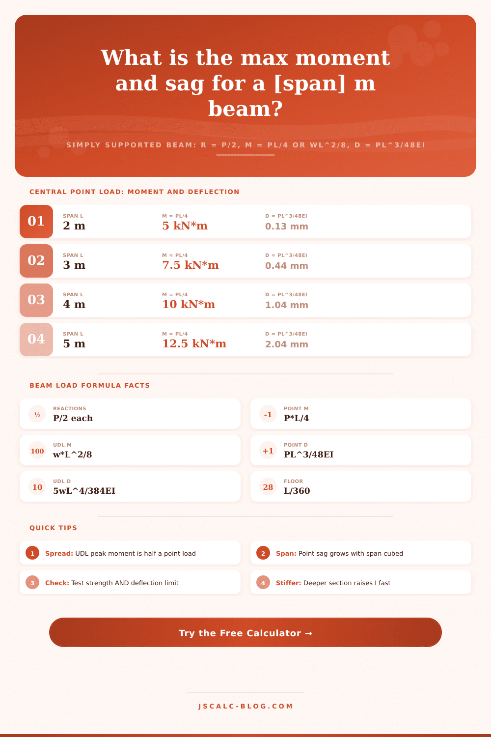
| 2 m | 5 kN*m | 0.13 mm | 2.5 kN*m | 0.03 mm | L/15400 |
| 3 m | 7.5 kN*m | 0.44 mm | 5.6 kN*m | 0.13 mm | L/6840 |
| 4 m | 10 kN*m | 1.04 mm | 10 kN*m | 0.42 mm | L/3850 |
| 5 m | 12.5 kN*m | 2.03 mm | 15.6 kN*m | 0.81 mm | L/2460 |
| 6 m | 15 kN*m | 3.52 mm | 22.5 kN*m | 1.41 mm | L/1710 |
| 8 m | 20 kN*m | 8.33 mm | 40 kN*m | 3.33 mm | L/960 |
Basis: P = 10 kN point OR w = 5 kN/m UDL, steel E = 200 GPa, I = 8e-5 m⁴. Notice UDL sag stays smaller and point sag climbs steeply with span.
✅Deflection Serviceability Limits
| Limit | Ratio | Allowed d at L = 4 m | Allowed d at L = 6 m | Typical Application |
|---|---|---|---|---|
| L/180 | Loose | 22.2 mm | 33.3 mm | Rough framing, total load |
| L/240 | General | 16.7 mm | 25.0 mm | Roofs, floors total load |
| L/360 | Standard | 11.1 mm | 16.7 mm | Floors, live load, plaster |
| L/480 | Strict | 8.3 mm | 12.5 mm | Brittle finishes, tile |
| L/600 | Very strict | 6.7 mm | 10.0 mm | Sensitive equipment |
⚙Formula Breakdown
💡Beam Load Design Tips
The beam is adequate in strength to support the weight of the roof, yet it’s too saggy (meaning it lacks stiffness) for your livig room ceiling. It may seem unlikely, but it’s more common then you’d expect, particularly if you’re inspecting an aged floor joist that sags beneath your feet or sizing a header across newly cut doorway. A beam must be stiff as well as strong. One prevents collapse; the other prevents trampoline-like behavior.
The calculator up top account for this tug-of-war between stiffness and strength, without making you derive it from scratch each time you sketch out a rough idea. From there we move to more complex structures: the classic one would be a simply supported beam resting on two supports which push upwards on it but do not oppose its rotation. They is effectively a roller on one end and a pin on the other, allowing the member to swing freely with no buildup of complicated end moments.
Why Beams Need Strength and Stiffness
So the physics becomes simple. There are equal and opposite reactions upwards at both ends balancing the total downwards load. That’s the simple vertical balance that all calculations come from. There is four different stories those outputs tell you about that balance. The reactions show you how hard the supports must push up. The shear force tells you what the inside of the beam are doing as it tries to slice itself apart around those supports. The bending moment measure the amount of curling action the load has on the member. It makes the member want to curl into a U. This tell you how deep or how thick a section you will need. Deflection is the sag you see, the part that cracks plaster and worries your neighbors.
It’s the one you worry about, but you need them all to feel good about your design. Where you load it matter. Maximum bending moment happen at the worst case: a concentrated heavy load dead center. Stress peaks immediately below this load. Uniformly distribute the same total load across your span (the distributed load), and it will drop your maximum moment in half. That’s the benefit of increasing intermediate support points, or distributing a machine weight across a wider bearing plate. It’s also one of the least expensive ways to reduce stress without purchasing an oversized beam. You can select from these cases with the calculator and get a direct comparison of how much distribution relieves your span.
Span length is the silent killer in beam design. A longer span does not deflect proportionally to its length. Sag increases with the cube of the span for a point load. So when you double the span length, the sag becomes eight times greater. When under a uniform load, deflection increases at the rate of the fourth power. So doubling the span result in sixteen times the sag. On the other hand, the moment only increases by the square (or less) of the span. Hence a short beam can be quite rigid compared to a long beam of the exact same steel.
As far as material goes, not only does it matter for strength, but also for stiffness. For example, steel has an extremely high modulus of elasticity which means it’s very rigid. On the other hand aluminum will bend significantly further under the same load due to its lower stiffness but it’s also light. Depending on wood type and grade, it’s somewhere in-between. These is available in the reference table on the page. That way you can swap out materials and get a feel for the impact to the ultimate sag.
Geometry isn’t something that should of be ignored either. Depth plays a large role here since it’s cubed in the equation for moment of inertia. So while a wide beam may resist bending well, a deep one resists bending MUCH better. There are serviceability limits (L/360) for good reason. They ensure floors do not bounce and ceilings do not crack. You can build comfortabley buildings only when your deflection meets those ratios, and you shouldn’t compromise on that. The tool will automatically check yours against them and flag it if you’re over.
It’s easy to build for strength without thinking about comfort. Do both. Combining strength with a solid appearance is what turns your sketch into a safe building.