Voltage Drop Calculator
Estimate conductor voltage drop, percent drop, voltage at the load, and NEC compliance for copper or aluminum wire using the circular-mil resistivity method for DC, single-phase, and three-phase circuits.
⚡Real Wiring Presets
🔌Circuit Inputs
Distance from source to load; the formula doubles it for the return path.
Use 1.0 for resistive loads; ignored for DC systems.
🔢Formula Snapshot
📏AWG Circular Mils & Resistance
| Wire Size | Circular Mils | Copper Ω/1000ft | Aluminum Ω/1000ft | Typical Use |
|---|---|---|---|---|
| 14 AWG | 4,107 | 3.14 | 5.17 | 15A lighting |
| 12 AWG | 6,530 | 1.98 | 3.25 | 20A receptacles |
| 10 AWG | 10,380 | 1.24 | 2.04 | 30A dryer/AC |
| 8 AWG | 16,510 | 0.778 | 1.28 | 40A range |
| 6 AWG | 26,240 | 0.491 | 0.808 | 55A feeder |
| 4 AWG | 41,740 | 0.308 | 0.508 | 70A subpanel |
| 2 AWG | 66,360 | 0.194 | 0.319 | 95A service |
| 1/0 AWG | 105,600 | 0.122 | 0.201 | 125A feeder |
| 2/0 AWG | 133,100 | 0.0967 | 0.159 | 150A service |
| 4/0 AWG | 211,600 | 0.0608 | 0.100 | 200A service |
📊NEC Recommended Drop & Ampacity
| Circuit Type | NEC Guidance | Recommended Drop | Example System | Max Drop (V) |
|---|---|---|---|---|
| Branch circuit | 210.19(A) note | 3% max | 120 V | 3.6 V |
| Feeder only | 215.2(A) note | 3% max | 240 V | 7.2 V |
| Feeder + branch | Combined note | 5% max | 120 V | 6.0 V |
| Sensitive load | Design practice | 2% max | 208 V | 4.16 V |
| Motor branch | 430 general | 3% max | 480 V | 14.4 V |
| Low-voltage DC | Design practice | 3% max | 12 V | 0.36 V |
| Wire Size | Copper 60°C | Copper 75°C | Aluminum 75°C | Common Breaker |
|---|---|---|---|---|
| 14 AWG | 15 A | 20 A | -- | 15 A |
| 12 AWG | 20 A | 25 A | 20 A | 20 A |
| 10 AWG | 30 A | 35 A | 30 A | 30 A |
| 8 AWG | 40 A | 50 A | 40 A | 40 A |
| 6 AWG | 55 A | 65 A | 50 A | 50 A |
| 4 AWG | 70 A | 85 A | 65 A | 70 A |
| 2 AWG | 95 A | 115 A | 90 A | 90 A |
| 1/0 AWG | 125 A | 150 A | 120 A | 125 A |
| 2/0 AWG | 145 A | 175 A | 135 A | 150 A |
| 4/0 AWG | 195 A | 230 A | 180 A | 200 A |
🗂Voltage Drop Comparison Grid
| Scenario | Wire | Amps | Length | Voltage | Approx Drop | Percent |
|---|---|---|---|---|---|---|
| Kitchen receptacle | 12 AWG Cu | 20 A | 100 ft | 120 V | ~7.9 V | ~6.6% |
| Detached shop feed | 10 AWG Cu | 30 A | 150 ft | 240 V | ~11.2 V | ~4.7% |
| EV charger circuit | 6 AWG Cu | 50 A | 60 ft | 240 V | ~3.0 V | ~1.2% |
| Subpanel feeder | 2 AWG Cu | 100 A | 120 ft | 240 V | ~4.7 V | ~1.9% |
| Well pump run | 10 AWG Cu | 12 A | 250 ft | 240 V | ~7.5 V | ~3.1% |
| Landscape lighting | 12 AWG Cu | 8 A | 80 ft | 12 V | ~2.5 V | ~21% |
| Aluminum feeder | 4 AWG Al | 90 A | 110 ft | 240 V | ~10.1 V | ~4.2% |
| Motor branch 3ph | 8 AWG Cu | 40 A | 200 ft | 480 V | ~8.1 V | ~1.7% |
⚙Full Formula Breakdown
📋Reference Values
| Material | K (ohm-cmil/ft) | Relative Drop | Notes |
|---|---|---|---|
| Copper | 12.9 | Baseline | Standard building wire, best conductivity per size |
| Aluminum | 21.2 | ~1.64× more | Common for feeders; upsize to match copper drop |
| Copper-clad Al | ~16.0 | ~1.24× more | Less common; between copper and aluminum |
| Silver (ref) | ~11.0 | ~0.85× | Best conductor but rarely used in building wire |
💡Practical Wiring Tips
Flipping a switch doesn’t just cause lights to dim; they vanish. Physics is against bad planning, so well pump struggles along until it shuts down altogether. Electricity are stolen on its way to where it is being used. The further away from the panel, the smaller the wire, the higher the loss… but how much?
This calculator figures math for you: how far can electricity make it before it’s all used up? Knowing these figure helps keep your equipment running well and safely.
How to Choose the Right Wire Size
The resistance are present with every conductor and resists flow of electricity. In electrical terms it’s driven by length and wire gauge. For wire, the cross-sectional area of the strand (copper/aluminum) is measured in something called circular mils. The higher the number, the more metal you have for electrons to pass through; therefore, the lower the resistance. Increasing the wire size by one step reduce the resistance because the shape change. No hidden trick in the code here.
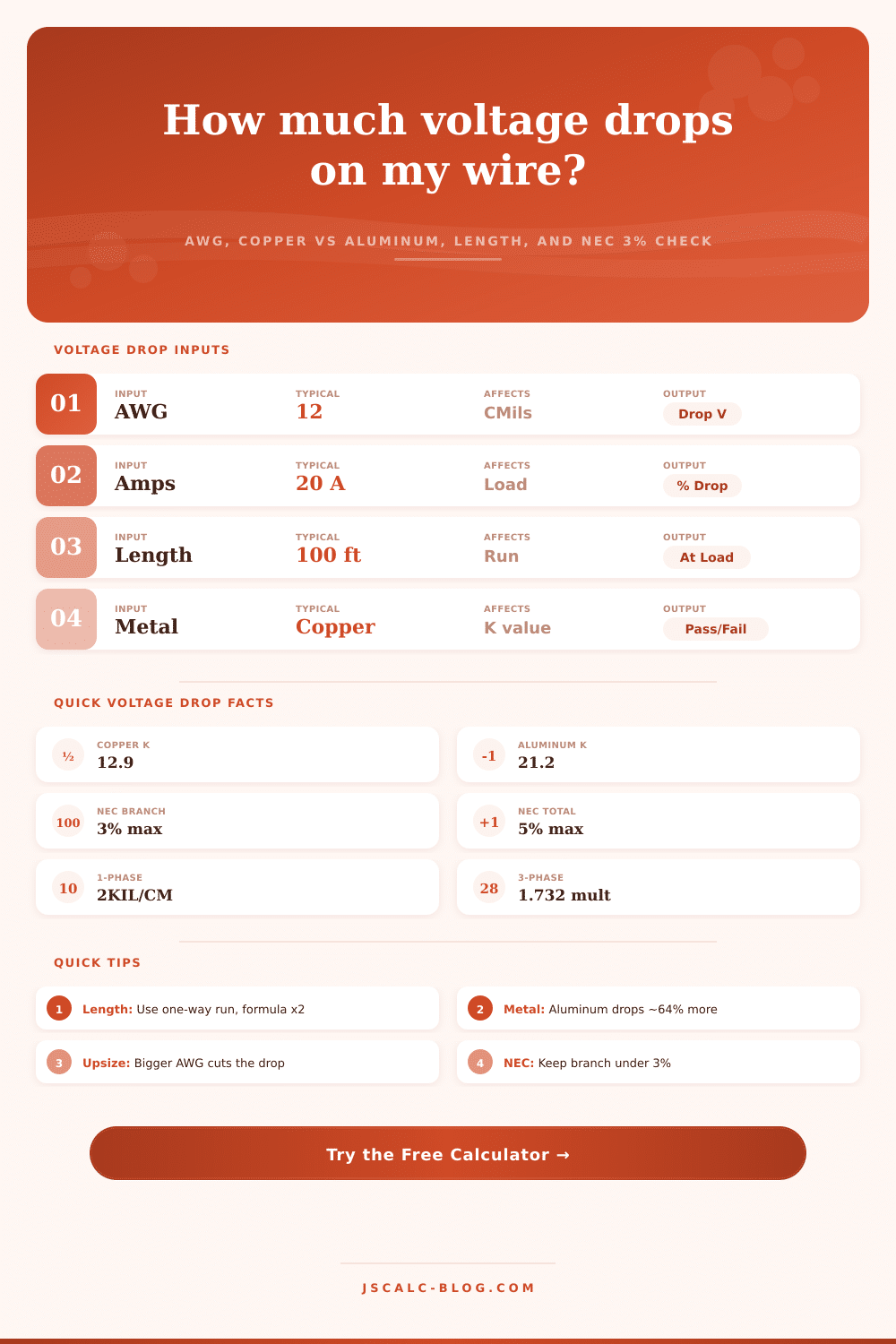
Just as important as size is material you choose. Copper will cost more and weigh more but, for any given physical size, it transmits roughly 64 percent more efficient than aluminum. So you can’t just substitute one for another without accounting of this fact. The calculator uses a resistivity constant of typically 12.9 for copper and 21.2 for aluminum. In other words, if you try to save some cash up front by going with aluminum instead, your gauge must be bigger down the road to get equivalent performance.
Branch circuits is relatively short runs of wire. This means voltage drop remain reasonable on smaller copper gauges, so most homeowners go with that metal. Most DIYs gets burned by length. They measure it (point A to point B), put that into the calculator and then overlook fact that electricity must return. For DC and single-phase systems, formula basically doubles the length as current flows out to device and returns via a neutral wire. That means if you run one-hundred feet of cable, electrons have to cover two-hundred feet total.
Folks will see voltage decrease by say.01 per foot and think overall loss isn’t significant. With high-draw appliances such as an air conditioner or electric dryer, losses builds up rapidly when considering the round trip. The National Electrical Code makes recommendations rather than mandating hard-and-fast rules. Its suggestions include no more than a three-percent voltage drop for branch circuits and a five-percent total voltage drop for the feeder-plus-branch circuit. These aren’t hard and fast rules, but they is guidelines for performance, not for fire prevention.
If voltage is too low, you might not trip a breaker but you will draw more current which overheats motor. Motors require full voltage to get correct torque. Operating motors on low voltage means the motor work harder, wears out quicker and runs poorly. These include variable-speed drives, sensitive electronics, and LED lighting. Forget it. They’ll flat-out refuse to operate, turn off without warning or simply blink out of existance.
Real-world limitations is made vivid by the calculator’s pre-programmed scenarios. If you have a landscape lighting loop or plan to feed a subpanel at opposite end of a big yard, use the same logic. Make sure wire is thick enough for the run. Match the material to the load and repeat. It’s not rocket science. It’s making sure the device gets just enough power from right source to do its job.
Result? This provides quiet, worry-free, and reliable power that never asks for anything.