Radio Antenna Length Calculator
Enter a frequency in kHz, MHz or GHz and pick an antenna type to get the free-space wavelength, the trimmed physical element length, the per-leg length for a dipole, and the radio band name, all adjusted by the velocity factor of your conductor.
🎯Real Antenna Presets
📡Antenna Inputs
The center frequency your antenna must resonate on.
1 GHz = 1000 MHz, 1 MHz = 1000 kHz.
Sets which multiple of the wavelength is built.
Wire is about 0.95; bare tubing nearer 0.97.
Choose how the length cards are displayed.
Controls rounding on the meter values.
🔢Formula Snapshot
📋Radio Bands and Frequency Ranges
| Band | Frequency Range | Wavelength Range | Typical Use |
|---|---|---|---|
| LF | 30 to 300 kHz | 10 to 1 km | Navigation, time signals |
| MF / AM | 300 kHz to 3 MHz | 1000 to 100 m | AM broadcast radio |
| HF / Shortwave | 3 to 30 MHz | 100 to 10 m | Ham, CB, shortwave |
| VHF | 30 to 300 MHz | 10 to 1 m | FM, TV, 2m ham, air |
| UHF | 300 MHz to 3 GHz | 1 m to 10 cm | TV, 70cm, cell, WiFi |
| SHF / Microwave | 3 to 30 GHz | 10 to 1 cm | WiFi 5 GHz, radar, sat |
📏Antenna Type Length Formulas
| Antenna Type | Fraction of Lambda | Meters (with VF) | Feet (handy form) |
|---|---|---|---|
| Quarter-wave vertical | 0.25 lambda | VF × 299.79 / (4 f) | 234 / f MHz |
| Half-wave dipole (total) | 0.5 lambda | VF × 299.79 / (2 f) | 468 / f MHz |
| Dipole per leg | 0.25 lambda | VF × 299.79 / (4 f) | 234 / f MHz |
| Full-wave loop | 1.0 lambda | VF × 299.79 / f | 984 / f MHz |
| 5/8-wave vertical | 0.625 lambda | VF × 187.37 / f | 585 / f MHz |
🧩Velocity Factor by Conductor
| Conductor / Material | Velocity Factor | Where It Applies | Note |
|---|---|---|---|
| Ideal in free space | 1.00 | Theory only | Speed of light exactly |
| Bare aluminum tubing | 0.96 to 0.98 | Verticals, beams | Thick elements |
| Insulated copper wire | 0.94 to 0.96 | Dipoles, wire loops | 0.95 is the common default |
| Thin enameled wire | 0.95 to 0.97 | Small loops, coils | Depends on diameter |
| Loaded / coil-shortened | 0.60 to 0.90 | Mobile whips | Loading lowers effective VF |
🗃Frequency to Length Comparison Grid
| Frequency | Wavelength | Quarter-wave (VF 0.95) | Half-wave Dipole | Dipole Leg | Band |
|---|---|---|---|---|---|
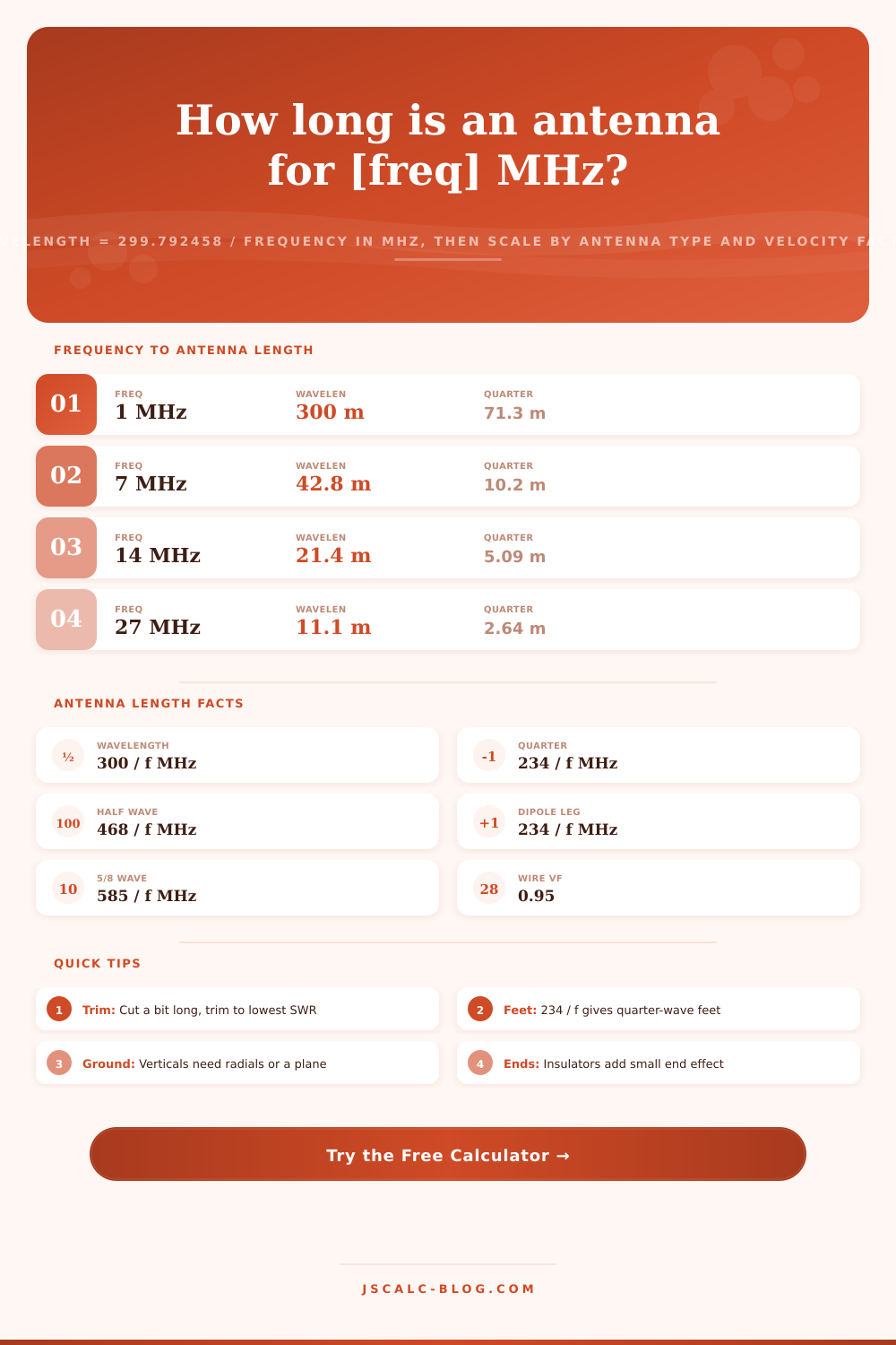
| 1.0 MHz | 299.8 m | 71.20 m | 142.40 m | 71.20 m | MF / AM |
| 7.1 MHz | 42.22 m | 10.03 m | 20.05 m | 10.03 m | HF |
| 14.2 MHz | 21.11 m | 5.01 m | 10.03 m | 5.01 m | HF |
| 27.0 MHz | 11.10 m | 2.64 m | 5.27 m | 2.64 m | HF / CB |
| 50.0 MHz | 6.00 m | 1.42 m | 2.85 m | 1.42 m | VHF |
| 100 MHz | 3.00 m | 0.712 m | 1.424 m | 0.712 m | VHF / FM |
| 146 MHz | 2.053 m | 0.487 m | 0.975 m | 0.487 m | VHF |
| 446 MHz | 0.672 m | 0.160 m | 0.319 m | 0.160 m | UHF |
| 915 MHz | 0.328 m | 0.078 m | 0.156 m | 0.078 m | UHF |
| 2400 MHz | 0.125 m | 0.0297 m | 0.0593 m | 0.0297 m | UHF / WiFi |
⚙Formula Breakdown
💡Antenna Building Tips
This page turns a frequency into the exact physical size of an element in seconds using its radio antenna length calculator. A radio antenna is not just a random piece of tubing or wire. Instead, it’s cut to some fraction of the radio wavelength that makes it efficient at resonating and radiating your desired frequency.
Simply enter a frequency in GHz, MHz or kHz. Select the antenna type you want to build and specify a velocity factor. The tool then provides the radio band for the signal, the free-space wavelength, the trimmed element length, and if it is a dipole, the length of each leg. Knowing versus guessing, it’s the difference.
How to Calculate Antenna Size
Here is a quick refresher in basic physics. We all learn early on that antenna length vary with frequency. Why? Here’s the answer: At the speed of light, a radio wave travels. Oscillate more quickly and it’ll cover less distance with each cycle. That distance between cycles is called the wavelength, and it’s the thing everything else you’ll ever do will depend on.
792458 divided by the frequency in megahertz. An FM signal of 100 MHz means the wavelength is roughly 3 meters long. Or about 12.5 centimeters. And that’s why any good antenna are made to be a fraction of its wavelength, making high-frequency signals have much smaller antennas.
Make a big enough one for AM broadcast and the antenna tower becomes huge; make one small enough for a handheld radio and the antenna goes short. The math doesn’t change, just the scale. That’s why we begin with the free-space wavelength. If you enter something in kilohertz, the calculator scales it to megahertz first.
After that, all you have to do is take that wavelength and divide by some fraction (except for full-wavelength loops, which are simply one wavelength). Half-wave dipoles is a half-wavelength long. Quarter-wave elements are a quarter-wavelength long. This pattern continues. Because they’re all fractions, each type of antenna uses the same frequency but with an antenna of a completely different size.
You don’t have to remember how this works; the calculator above does it for you, sparing you the need to keep a scientific calculator handy while holding a tape measure against the wall. If you think about it, when a wave goes from free space to a real conductor, the distance traveled is reduced a bit because the wave slows down as it go over the conductor. This means that a physical antenna needs to be just a hair smaller than the raw math says it should of been.
The velocity factor is a number smaller than one which shows that reduction in length. For insulated copper wire, it’s roughly 0.95. Bare aluminum tubing is more like 0.97. Mobile whips coiled with lots of loading elements will be much lower still. Your selected velocity factor gets multiplied into the calculated ideal length. This is what makes all the difference between having an antenna that hits its target frequency versus missing the band altogether. It is a small tweak, but it is very important to get it right.
The tool has each type of antenna defined with the purpose they serve. For example, the half wave dipole is a classic wire antenna with two equal legs that are split from the center and fed there. That’s why you see the length of each leg reported as half the overall length. A quarter wave vertical is compact and can be used over a ground plane or radiating radials, making it popular for both base and mobile vertical antennas. A full wave loop provides a quieter recieve signal along with some gain. On UHF and VHF, the 5/8 wave vertical concentrates signal off to the horizon providing better range. Choosing one of these changes the fraction of wavelength selected, and all results cards updates immediately.
Long ago radio operators came up with some simple formulas that incorporate a normal velocity factor into one number. Here are the two quick ones: If it’s a dipole (half wave), then for a dipole in feet divide 468 by the frequency in megahertz. If it’s a quarter wave, like an element on a Yagi antenna, divide 234 by the frequency in megahertz. That’s how you get a 40 meter band dipole coming out at roughly 66 feet if you’re working at say around 7.1 MHz. The calculator breaks this down and gives you a handy number to crosscheck the metric answer different than your own rule of thumb. It is good to have both worlds covered.
So what did we get? Four result cards sum up the calculation. First, the wavelength card provides the complete free-space lambda at your frequency. Second, the element length card provides the physical length after trimming to fit whatever antenna you chose. Third, the per-leg card returns half of the dipole total, and this is the one number you cut most often in practice. Fourth, the band card labels the region of the spectrum. Finally, there’s a detailed breakdown panel with all the numbers it replaced; the tool can serve as a check against hand calculations.
Note that resonance can be altered by nearby metal, height off the ground, and even how resonant ends are insulated, so think of the number as a starting guideline for build instead of a cut list to the end. Make each piece just a bit longer. Then trim, one little piece at a time, listening for the dip to land on your desired frequency.
To get a vertical antenna working properly, you will need radials or another good grounding plane. Whether you’re a ham cutting his first dipole, a hobbyist wanting to size out an IoT antenna, or a broadcast receiver builder, starting with reliable element and wavelength figures is job zero. After that, you need a good set of wire cutters and a lot of patience.