Voltage Drop Across a Resistor Calculator
Apply Ohm's law V = I x R to find the voltage dropped across a resistor and the power it dissipates, size an LED series resistor from your supply voltage and LED forward voltage with R = (Vs - Vf) / I, or solve a two resistor voltage divider for its output voltage and current.
🔌Choose a Mode
🎯Real Circuit Presets
📝Circuit Inputs
Source voltage feeding the resistor or LED branch.
Ohm's law mode: resistor whose drop you want.
Ohm's law mode: current through the resistor in milliamps.
Voltage the LED itself drops; depends on colour.
Target forward current, usually 10 to 20 mA.
Divider mode: resistor between Vs and the output tap.
Divider mode: resistor between the tap and ground.
Controls how result cards and the breakdown display.
🔢Formula Snapshot
📋Standard E12 Resistor Values
| Base Value | x10 Decade | x100 Decade | x1k Decade |
|---|---|---|---|
| 10 ohm | 100 ohm | 1 k | 10 k |
| 12 ohm | 120 ohm | 1.2 k | 12 k |
| 15 ohm | 150 ohm | 1.5 k | 15 k |
| 18 ohm | 180 ohm | 1.8 k | 18 k |
| 22 ohm | 220 ohm | 2.2 k | 22 k |
| 27 ohm | 270 ohm | 2.7 k | 27 k |
| 33 ohm | 330 ohm | 3.3 k | 33 k |
| 39 ohm | 390 ohm | 3.9 k | 39 k |
| 47 ohm | 470 ohm | 4.7 k | 47 k |
| 56 ohm | 560 ohm | 5.6 k | 56 k |
| 68 ohm | 680 ohm | 6.8 k | 68 k |
| 82 ohm | 820 ohm | 8.2 k | 82 k |
💡LED Forward Voltage by Colour
| LED Colour | Typical Vf | Range | Notes |
|---|---|---|---|
| Infrared | 1.4 V | 1.2 - 1.6 V | Remote controls |
| Red | 2.0 V | 1.8 - 2.2 V | Lowest of visible |
| Yellow | 2.1 V | 2.0 - 2.2 V | Similar to red |
| Green | 2.2 V | 2.0 - 3.0 V | Pure green higher |
| Orange | 2.0 V | 1.9 - 2.1 V | Close to red |
| Blue | 3.2 V | 3.0 - 3.4 V | Needs less R |
| White | 3.2 V | 3.0 - 3.4 V | Blue die plus phosphor |
| UV | 3.4 V | 3.1 - 3.7 V | Highest common Vf |
🔧Resistor Power Rating Guide
| Rating | In Watts | Safe Continuous | Typical Use |
|---|---|---|---|
| 1/8 W | 0.125 W | up to 0.06 W | Signal, small LEDs |
| 1/4 W | 0.25 W | up to 0.12 W | Most hobby circuits |
| 1/2 W | 0.5 W | up to 0.25 W | Higher current LEDs |
| 1 W | 1.0 W | up to 0.5 W | Power resistors |
| 2 W | 2.0 W | up to 1.0 W | Loads, bleeders |
| 5 W | 5.0 W | up to 2.5 W | Wirewound, dummy load |
📊Ohm's Law Quick Reference
| Voltage V | Resistance R | Current I | Power P = V I |
|---|---|---|---|
| 3 V | 150 ohm | 20 mA | 60 mW |
| 5 V | 250 ohm | 20 mA | 100 mW |
| 3.3 V | 330 ohm | 10 mA | 33 mW |
| 12 V | 1.2 k | 10 mA | 120 mW |
| 5 V | 100 ohm | 50 mA | 250 mW |
| 9 V | 450 ohm | 20 mA | 180 mW |
| 1.2 V | 60 ohm | 20 mA | 24 mW |
| 24 V | 2.2 k | 10.9 mA | 262 mW |
🔌LED Series Resistor Comparison Grid
| Supply | LED Vf | Current | Resistor (calc) | Nearest E12 | Power |
|---|---|---|---|---|---|
| 5 V | 2.0 V (red) | 20 mA | 150 ohm | 150 ohm | 60 mW |
| 5 V | 3.2 V (blue) | 20 mA | 90 ohm | 82 ohm | 36 mW |
| 3.3 V | 2.0 V (red) | 15 mA | 86.7 ohm | 82 ohm | 19.5 mW |
| 9 V | 2.0 V (red) | 20 mA | 350 ohm | 390 ohm | 140 mW |
| 12 V | 2.0 V (red) | 20 mA | 500 ohm | 470 ohm | 200 mW |
| 12 V | 3.2 V (white) | 20 mA | 440 ohm | 470 ohm | 176 mW |
| 6 V | 3.4 V (UV) | 20 mA | 130 ohm | 120 ohm | 52 mW |
| 5 V | 2.1 V (yellow) | 10 mA | 290 ohm | 270 ohm | 29 mW |
| 24 V | 2.0 V (red) | 20 mA | 1.1 k | 1 k | 440 mW |
| 3.7 V | 3.2 V (blue) | 15 mA | 33.3 ohm | 33 ohm | 7.5 mW |
⚙Formula Breakdown
💡Resistor Selection Tips
It’s a problem as old as electronics: You’ve got some LEDs, a bag full of resistors whose color codes you can barely read, and somewhere a power supply. There’s just one thing missing; an LED that will light up without melting itself into oblivion unless connected directly to said power supply. Welcome to real world electronics, where theory collides with the dirty business of component tolerance.
Once you enters your desired current and voltage into calculator above, it’ll crunch the math for you. But knowing why the numbers apply will keep you from soldering together a circuit that appears correct but blows itself apart at first sign of load or heat. It’s simple enough to print onto a bumper sticker, ohm’s law, but it takes more than knowledge to apply it properley.
How to Choose the Right Resistor for LEDs
So the basic idea is that a resistor doesn’t store any of that energy; it just wastes it as heat. Voltage drop across resistors according to V = I x R, when current is flowing through them. So if you shove 20 milliamps through a 150 ohm resistor, the drop will be three volts. Increase the resistance by a factor of two and the drop at the same current double. Simple, right? Until you think about power. Thermal power equals how much energy gets wasted (P = I squared times R). In this case, the resistor would burn off 60 milliwatts. And it’s this number that determine whether your circuit lasts all night or melts its solder joints. That’s not much of a load for a typical quarter-watt resistor; no problem. However, when you crank the current to light a bright white LED, it doesn’t take long to double that power rating. And choosing a too-low-rated resistor is one of those oh-so-beginner mistakes that’ll cause things to smoke and then make troubleshooting difficult.
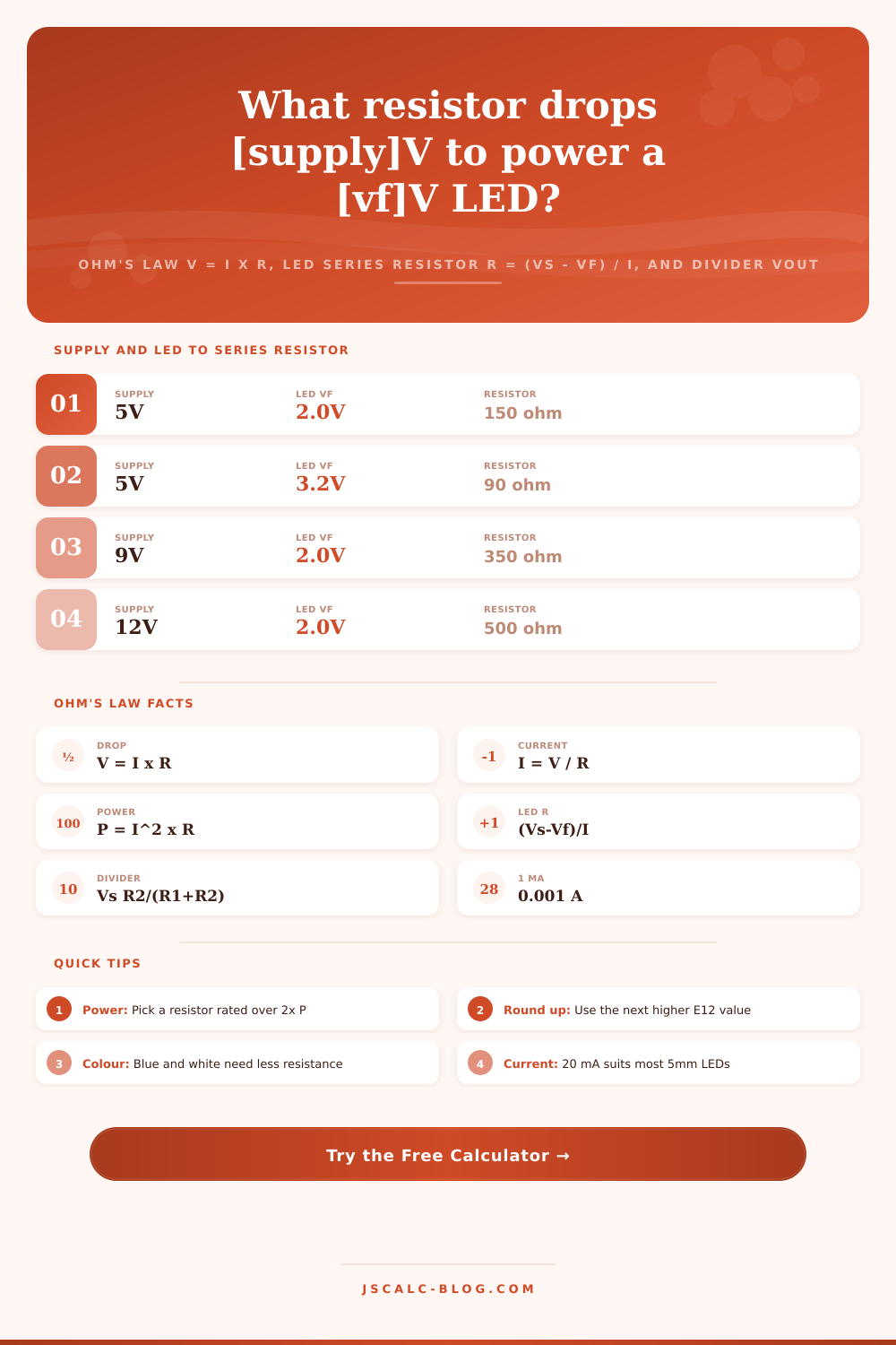
LEDs makes things complicated, however, as they’re not just resistors. They emit light, which means they also has a set forward voltage, typically around 1.8 volts on red ones and up to 3.4 volts in blue or white LEDs. Plugging an LED straight into a battery results in wild spikes of current until one thing or another break. To prevent that, you’ll want to include a series resistor to absorb the excess voltage. This tool calculates what you need by subtracting the LED’s forward voltage and dividing that by the desired current draw. So if you’ve got a five volt supply and run a red LED at 20 milliamps, you’ll need to soak up three volts across a resistor. The math give you 150 ohms.
In an ideal world, things work perfectly, but reality is different than what we expect. In the real world resistors are built with common values (called the E12 series). So while there’s no 90 ohm resistor on the shelf, there will be an 82 ohm one sitting right beside it. The calculator will round your answer to the closest available value (you don’t need to go hunting around in bins trying to get a perfect match.) Because of this rounding, a small error in current is introduced, which is generally fine for indicator lights but something you’ll want to keep an eye on if driving high power arrays or sensitive sensors. Always check the power dissipation after rounding up or down, as a slightly lower resistance means more current and more heat.
Another common use for this principle is with voltage dividers. You can take any supply voltage and divide it up proportionally using two resistors in series at their junction. This can be used to scale down a higher voltage signal that might damage a microcontroller. This makes it something that can be safely read by the microcontoller. As long as both resistors aren’t so high that you waste power or so low they introduce noise into the system, only the ratio of the two matter. If you have two identical 10k ohm resistor, then nine volts will be divided exactly in half. It wastes energy constantly drawing current from source, but it’s there for a reason.
It’s largely a matter of maintaining proper margins. Resistors should always be rated for at least twice their calculated value to keep them cool and make them last longer. And don’t assume all LEDs of one color act alike; remember that each manufacturer and even each batch will vary slightly from the next. Use the calculator as a good initial starting place, and your most useful tool will be a multimeter when testing actual voltages once assembled. If in doubt, you should of use the presets, adjust accordingly for your particular supply, and build confidently knowing you’ve got the physics on your side.