Shear Force and Bending Moment Calculator
Find support reactions, maximum shear force, and peak bending moment for a simply supported or cantilever beam under a single point load, a uniformly distributed load, or both combined by superposition.
🎯Real Beam Presets
📝Beam and Load Inputs
Distance between supports, or the free length for a cantilever.
Measured from the left support. For a cantilever, from the fixed end.
🔢Statics Snapshot
📊Shear and Moment at Key Points
| Section | Position x (m) | Shear V (kN) | Moment M (kN·m) | Note |
|---|---|---|---|---|
| Enter values above to generate the shear and moment table. | ||||
📐Standard Load Case Formulas
| Beam and Load | Left / Fixed Reaction | Right Reaction | Max Shear | Max Moment | Moment Location |
|---|---|---|---|---|---|
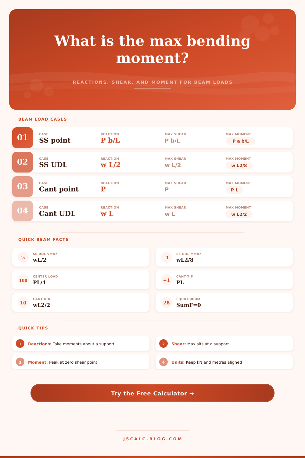
| SS, point P at center | P / 2 | P / 2 | P / 2 | P×L / 4 | Mid-span |
| SS, point P at a (b=L–a) | P×b / L | P×a / L | max(R_left, R_right) | P×a×b / L | Under the load |
| SS, UDL w over span | w×L / 2 | w×L / 2 | w×L / 2 | w×L² / 8 | Mid-span |
| Cantilever, point P at tip | P (at fixed end) | – | P | P×L | Fixed end |
| Cantilever, UDL w full | w×L (at fixed end) | – | w×L | w×L² / 2 | Fixed end |
| Cantilever, point P at a | P (at fixed end) | – | P | P×a | Fixed end |
🗂Beam Case Comparison Grid
| Scenario | Support | Load | Span L | Peak V | Peak M | Typical Use |
|---|---|---|---|---|---|---|
| Center point load | Simply supported | 20 kN @ mid | 6 m | 10 kN | 30 kN·m | Transfer beam under column |
| Off-center load | Simply supported | 25 kN @ 2 m | 6 m | 16.67 kN | 33.33 kN·m | Machine base support |
| Uniform floor | Simply supported | 5 kN/m UDL | 4 m | 10 kN | 10 kN·m | Residential floor joist |
| Bridge girder | Simply supported | 12 kN/m UDL | 10 m | 60 kN | 150 kN·m | Short-span deck girder |
| Balcony cantilever | Cantilever | 8 kN @ tip | 2.5 m | 8 kN | 20 kN·m | Projecting balcony beam |
| Canopy cantilever | Cantilever | 4 kN/m UDL | 3 m | 12 kN | 18 kN·m | Roof canopy overhang |
⚙Full Formula Breakdown
📋Sign Convention and Reference Guide
| Quantity | Symbol | Positive Sense | Where It Peaks | Units |
|---|---|---|---|---|
| Shear force | V | Upward left of section | At or near supports | kN |
| Bending moment | M | Sagging (concave up) | Where shear crosses zero | kN·m |
| Support reaction | R | Upward on the beam | Under heavier load side | kN |
| Point load | P | Downward gravity load | Applied at one section | kN |
| Distributed load | w | Downward per metre | Spread along the span | kN/m |
💡Practical Beam Tips
Next, you specify the type of beam. For most applications, it’s a simple “simply supported” beam that sits on two separate supports (e.g., bridge deck, floor joist). In contrast, cantilevered beams has a single fixed end with the other end being free (think diving board or balcony). That shifts all the physics.
Instead of the max bending moment being in the center as before, it’s now at the fixed end, where you see the beams gets thick and heavy right next to the wall. The calculator’s internal logic takes this all into account. However, it has to knows what kind of beam you want, or else you will use wrong formula for the beam.
Beam Types and Loads
Sometimes it is not just how much load but where you put it. If I have a simply supported beam with a heavy point load in the center, then the shear are evenly distributed. But if I slide that same load toward either support it has a dramatic effect on reaction forces. The near support bear most of the load and far support is relaxed. Novices often overlook that what happens here is asymmetrical. Designing for average loads fail to take both ends into account. Instead, the tool size the connection for each end specifically. A weak anchor on the heavily loaded end won’t necessarily break the beam; instead, it will fail first.
Uniform distributed loads (UDLs) are called distributed loads because they consist of weights, like furniture and people, spread across the structure. While point loads forms distinct peaks on shear diagrams, distributed loads will produce smooth curves on bending moment diagram. For a simply supported beam, the maximum moment from a UDL is always located at the midpoint of the span, making it much easier to check designs around this area. It’s safe to assume the middle is the key spot here.
Adding point loads to UDLs makes things tricky. Manual calculations becomes almost impossible without some sort of automation. This is why combined mode exists to handle these load combinations. They also mess up calculations.
If you mix feet with newtons or meters with kilograms, you end up either building the structure too light and running a high risk of it collapsing, or you overbuild it and waste money. Most structural codes operate in terms of kilonewtons and meters, which means keeping them all in kilonewtons and meters will keep things on track. Switching will automatically convert for you, although it’s still your job to check your units, since a misplaced decimal point can double your estimated bending moment, and that sort of mistake tends not to show itself until halfway through construction.
Critical points is where the shear force intersects zero; it’s also the point on the beam where the bending moment is maximum. Knowing this statics relationship can help you identify the danger spots without having to draw out a complete diagram each time. For instance, if you have an equal load across a span and you know the shear goes to zero in the middle of that span, you’ll want to put as much steel (or large timbers) there as possible. It’s simple math, but get these figures correct and you would of stability instead of collapse.